The Heavy Petter is an automated petting device that can be strapped onto a partner who is unwilling or unable to pet you for your desired length of time. It consists of two servo motors, an acrylic structure and a knitted casing. Please feel free to contact me if you have questions or suggestions for this tutorial.
Difficulty Level: Beginner/Intermediate
(coding and wiring are very Beginner, making the structure may prove challenging.)
Supplies
1.Structure Tests
2.Make the Structure
3.Program and Wire
4.Knit, Sew or Paint Casing
Supplies:
(note: if you don’t know where to buy these things, check out the resources page)
-2 small servo motors or hobby motors, 3-6 v
-1 Arduino Uno
-on/off button
-1 battery pack that holds 4 AA’s, to give 6 volts.
-1 9 volt battery clip
-1 blank pcb board for soldering
-1 breadboard for testing
-10-15 jumper wires for soldering and testing
-Soldering iron and solder
-18 x 24″ piece of plexi glass, cardboard, or other stiff material that you can cut with a knife of laser cutter.
-Balsa wood and/or cardboard for doing tests
-1 wooden dowel
-Yarn or Fabric
-Access to a laser cutter is helpful, but I did not use one for this project
-Power tools (Scroll saw, drill, band saw)
-Heat gun
The goal of the heavy petter is to move a human hand, with very little power. What’s the best way to do that? I thought about 3-D printing a gearbox, but when I made this piece I was at an artist’s residency in an isolated area (with no car), so I had limited resources. I watched this cool video on youtube https://www.youtube.com/watch?v=mkQ2pXkYjRM
And drooled. It’s mesmerizing.
Because I was making my structure with power tools (no fancy laser cutting this time!) I opted for a simple solution, which I will outline below. But if you get a better idea while testing, please do share!
The idea is based on the gear shown around 2 min. The motors are making a circular rotation, but the Motor Attachment has a Rod going through it, which is locked into the vertical cut-out in the Ribs. The motor attachment can pivot, which allows the Rod to move back and forth through the Ribs in a linear motion.
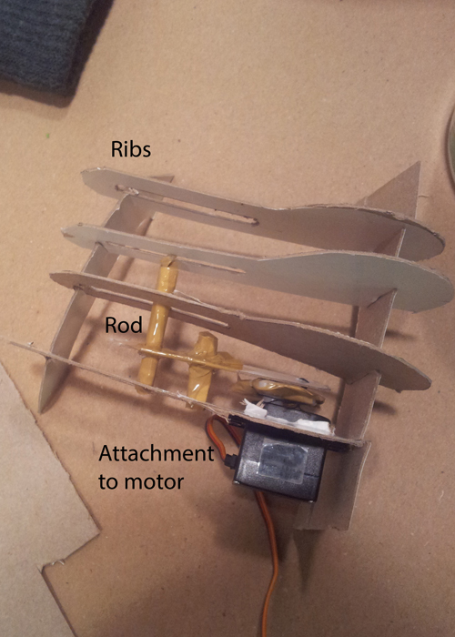
I decided to make 4 ribs with two motors on either side, so that one could line up roughly which each finger (thumb excluded).

I made tests in cardboard first to test the idea, and then I tried balsa wood to make modifications. I needed to change how long my different rib pieces were, because that would affect the distance the hand was pulled. I also had to take the curve out of the base design, because the straight rod could not move through a curve, it needed a flat plane.
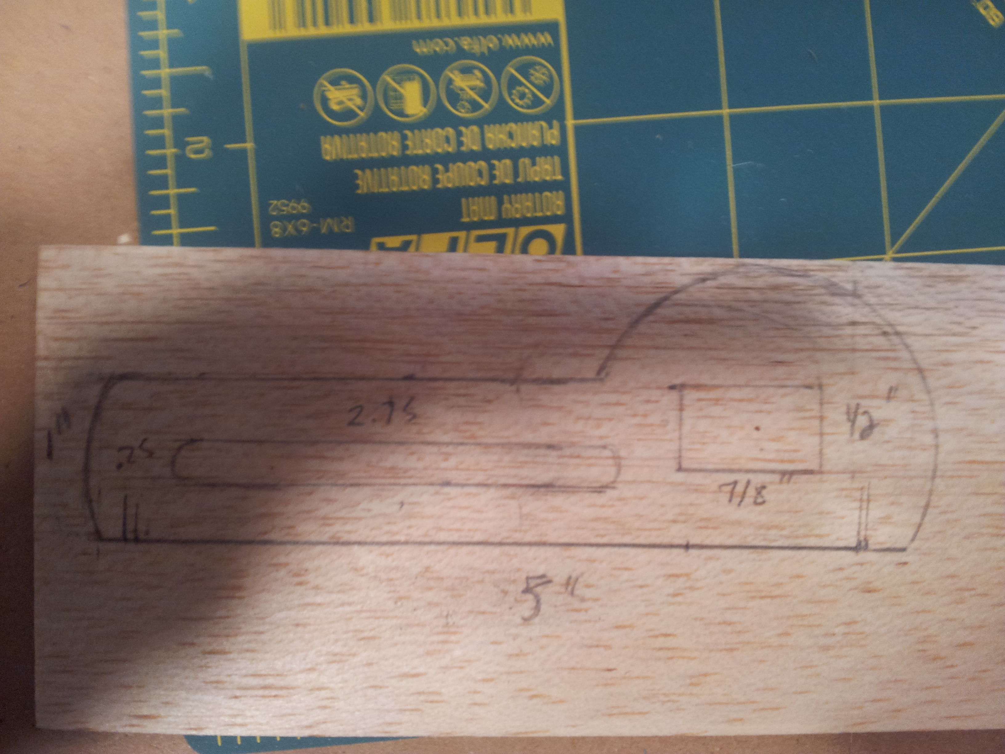
These are the rib measurements from my test, but the ribs were too short. I ended up making them 6 inches long, and they could’ve even been longer.
To understand if your tests are working well, it’s best to wire them up and turn them on, to see what kind of movement and resistance you are getting. Skip ahead to Program and Wire if you are ready to test. If you’re still confused about the structure, (I don’t blame you) keep reading, I have better photos coming up.
So I settled on this type of structure, and I made it out of acrylic. (clear acrylic of course, to make it all the harder to see. sorry!)
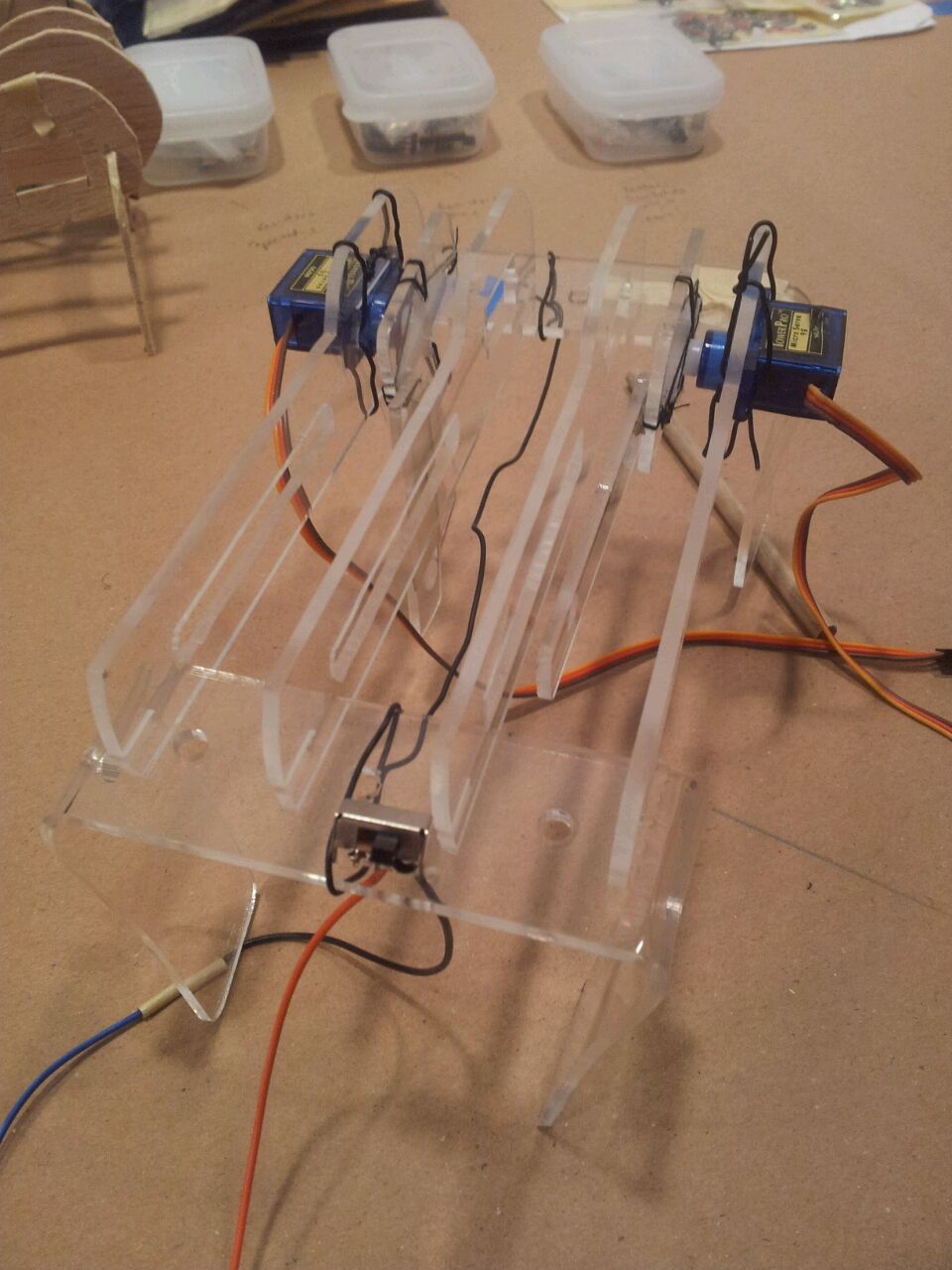
The structure consists of:
4 Ribs
2 Base pieces
1 Rod
2 Motor attachments
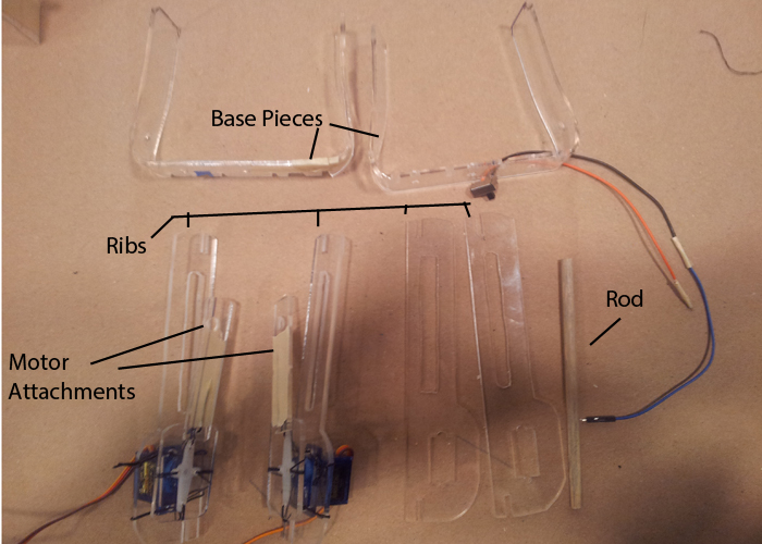
You can see they all have notches, to help them slot in together. This allows you to get away without glue, which is good because you want to be able to take it apart easily and make changes. Make your notches extra big if you’re going to knit a covering (see Knit, Sew or Paint Casing). Mine could’ve been bigger.
I made a guide for myself in Illustrator, to scale, you can see it below, and download the eps file here Then I printed it, cut out the pieces, and taped them to my acrylic, so that I’d be accurate when I cut my pieces out. Word to the wise: Use your cardboard or balsa wood tests as a guide. If using my guide, cut to the outside of the lines so you have extra room if you need to make changes, mine were a little tight.
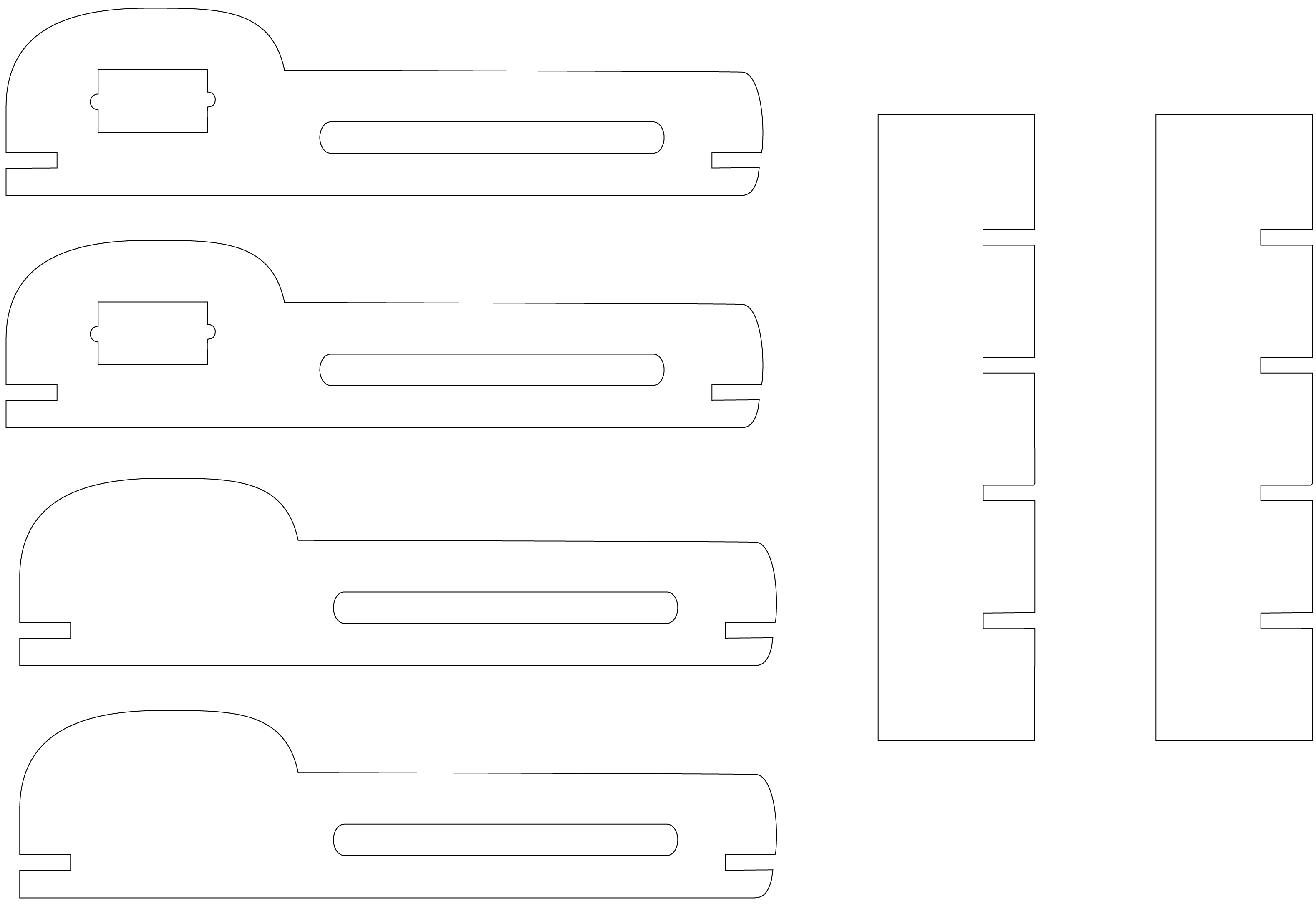
OH! I should note, the rectangles for the base pieces, the drawing shows only the middle part of each base piece, because I was using letter sized paper. In reality, they extend longer on either side, past the notches.
As you can see, two of the ribs need a square hole for the motor to pop through, I also added holes for the wires of the motors to slide through easily. This square should be accurate, so measure your servo motors carefully!

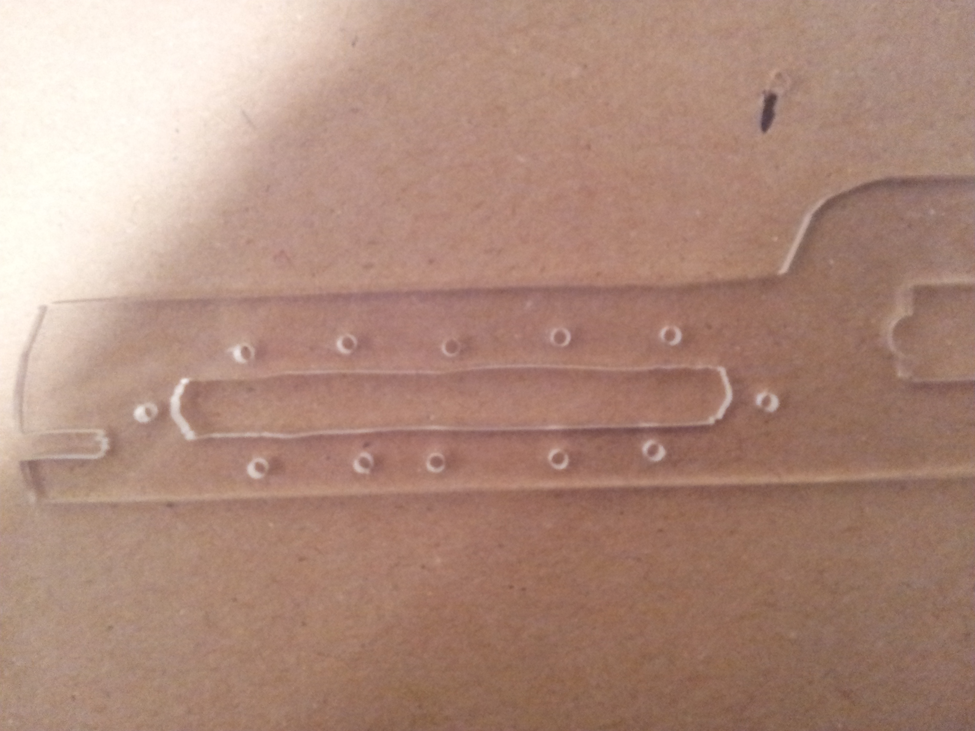
I cut them out using a band saw for the outside, and scroll saw for the inside.
It doesn’t have to look beautiful, because the structure will get covered, or at least mine did. I’m embarrassed by my crappy scroll saw job, I blame the ancient, rusty blade? But at any rate the holes work. I also drilled in tiny holes to make it easier to attach the fabric.
For the base pieces, you need to bend them with a heat gun after you cut them out, on either side of the outer notches, so you get two little legs. Make sure the four notches stay flat.
The motor attachment is actually in two pieces. The clear rectangle attached to the plastic cross is stationary, that bad boy clicks onto the motor. I drilled holes in the rectangle and attached the cross with string. Then the long piece you see there has a hole drilled through it for the rod, and a tiny hole for a piece of wire to pass through.

The rectangle and the rod need to be attached just by a piece of wire. Drill a tiny hole the size of your wire. Bend the wire at either end so it can’t slip out and secure it with a piece of tape. This allows the long piece to pivot. It needs to be able to pivot! Test that it can swing freely.

It can be a little finicky to get everything to line up, so I really recommend wiring it up and testing it, then taking it apart and making changes as needed.
The good news is, the wiring and programming are pretty darn easy!
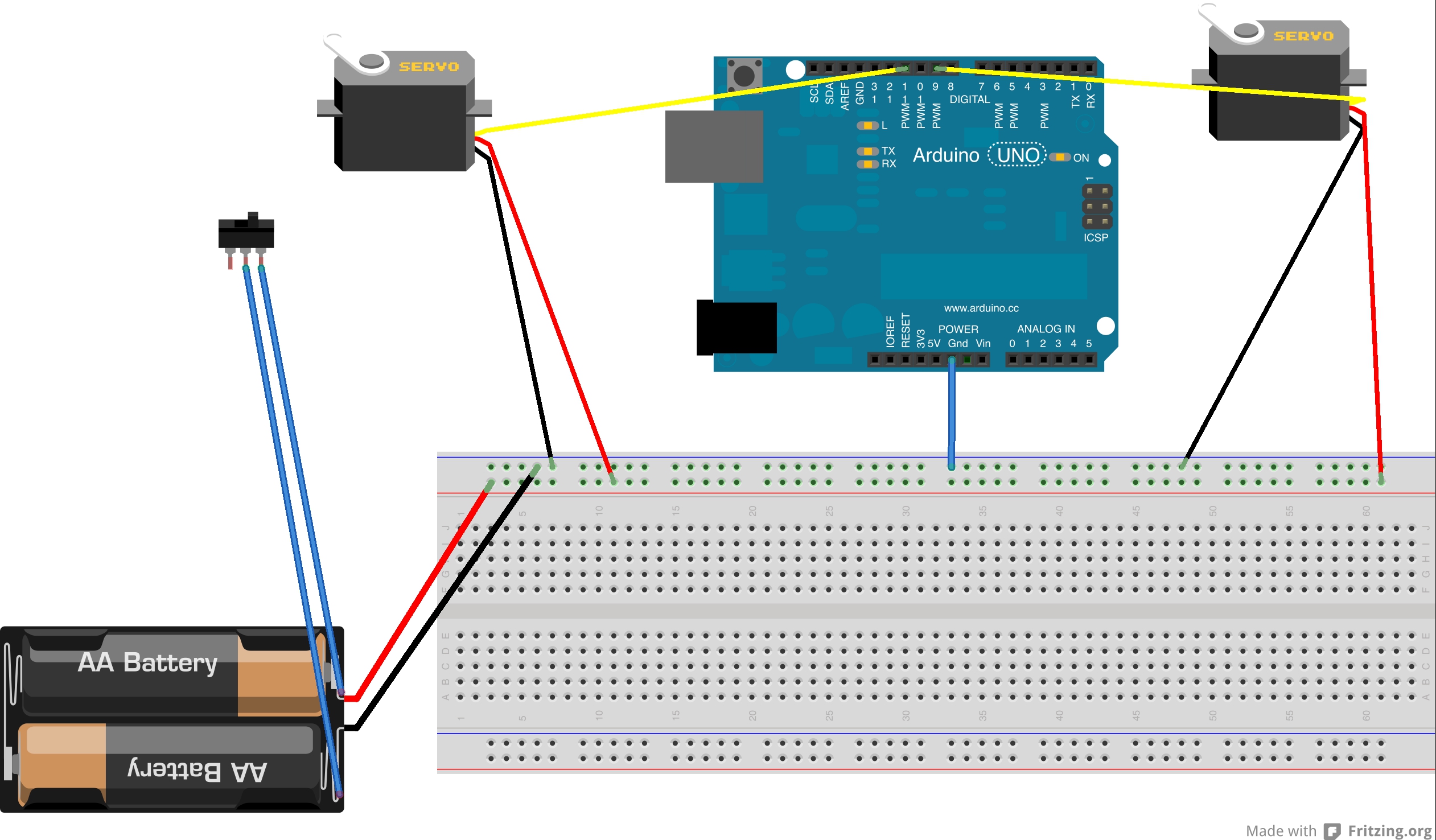
Straight forward! The servo motors need to be connected to the positive and ground on the breadboard. The communication pins can be connected to 9 and 11, or any pmw digital pin.
You may not know that it’s a good idea to separate your power supply! It’s a lot of strain on the Arduino to try to power two motors, so that’s why I use a separate battery back. There should be four double A there, not two. Just be sure to connect the ground on the Arduino, to the ground on the battery supply.
I added a button to my battery pack, so I can turn it on and off easily. The sketch is just a sweep loop, (sweep being one of the example sketches that comes with the Arduino program, check examples –> Servo –> Sweep) so if you turn the batteries off the motors will shut down, if you turn them on, they’ll keep moving. More photos of how I did that later.
As I said, the sketch is just sweep! Barely modified, except that there’s an added Servo, and longer delays.
#include <Servo.h>

Servo myServo;

Servo myServo2;

void setup() {

myServo.attach(9);

myServo2.attach(11);

}

void loop(){

myServo.write(0);

myServo2.write(180);

delay(1000);

myServo.write(180);

myServo2.write(0);

delay(1500);

}
When your structure is all assembled and your rod is attached, plug everything in and run the sketch to see how it looks and feels. Make any structural changes you need to (like cutting the openings bigger if the rod has too much resistance) before you solder.
When you feel comfortable that everything is working, then you can transfer your work to a blank piece of PCB and solder it up.
Here’s how the button worked:
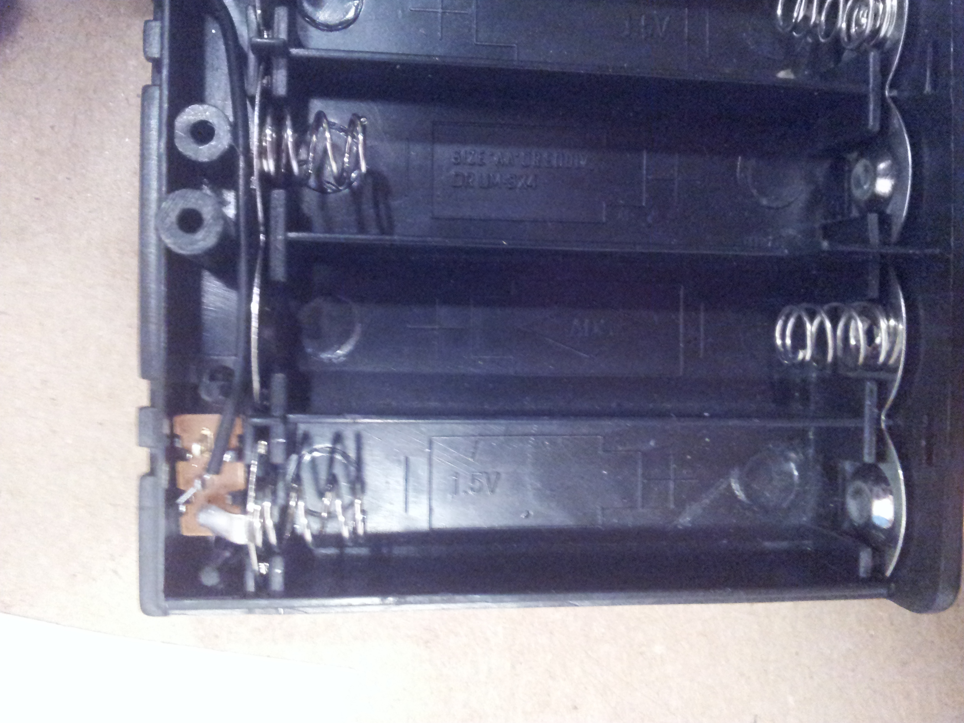
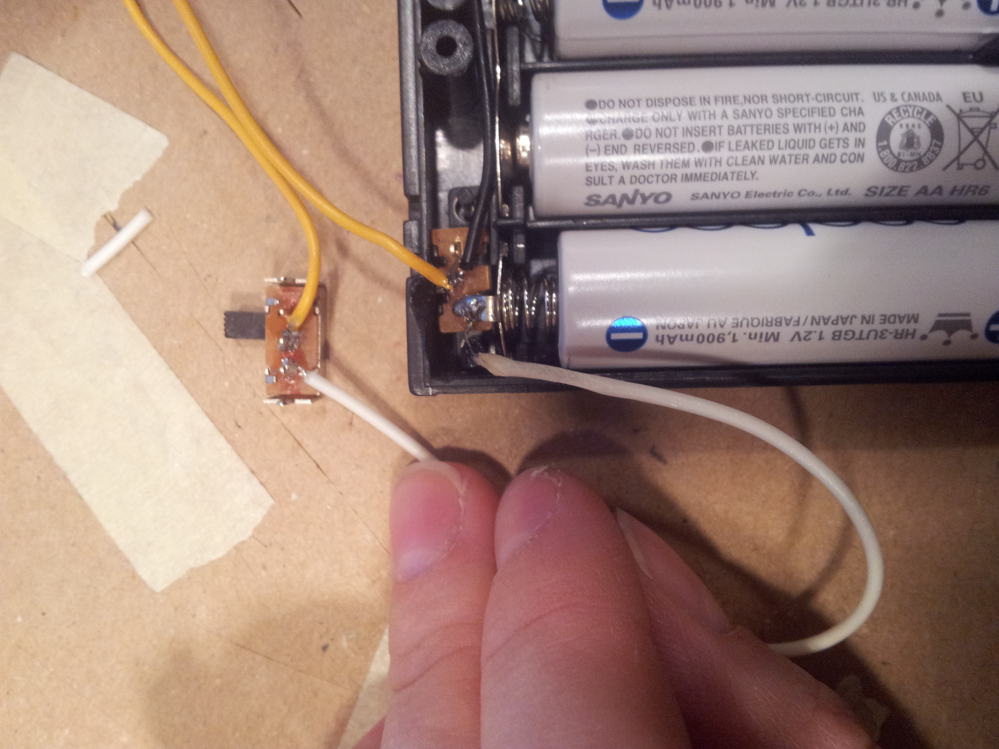
The white wire is connected to the positive terminal and the yellow wire is connected to the ground. The switch is off in the picture. If you click it forward, there will be a connection between positive and negative, and the pack will be “on”. (Take the batteries out when soldering!) I made my wires very long, so my switch could be on top of my Heavy Petter, even when the batteries were below the device.
Step 4: Knit, Sew or Paint Covering
I knit my covering! To be honest, I’m not sure if I’d recommend this to others because it was kind of a pain :). Another way might be just to cover it in fabric, or with a pretty contact paper.
I liked the way the big fluffy knitting looked though, I think a big bulky machine covered in knitting is kind of funny, so I didn’t mind putting in the labor. Anything for a joke.
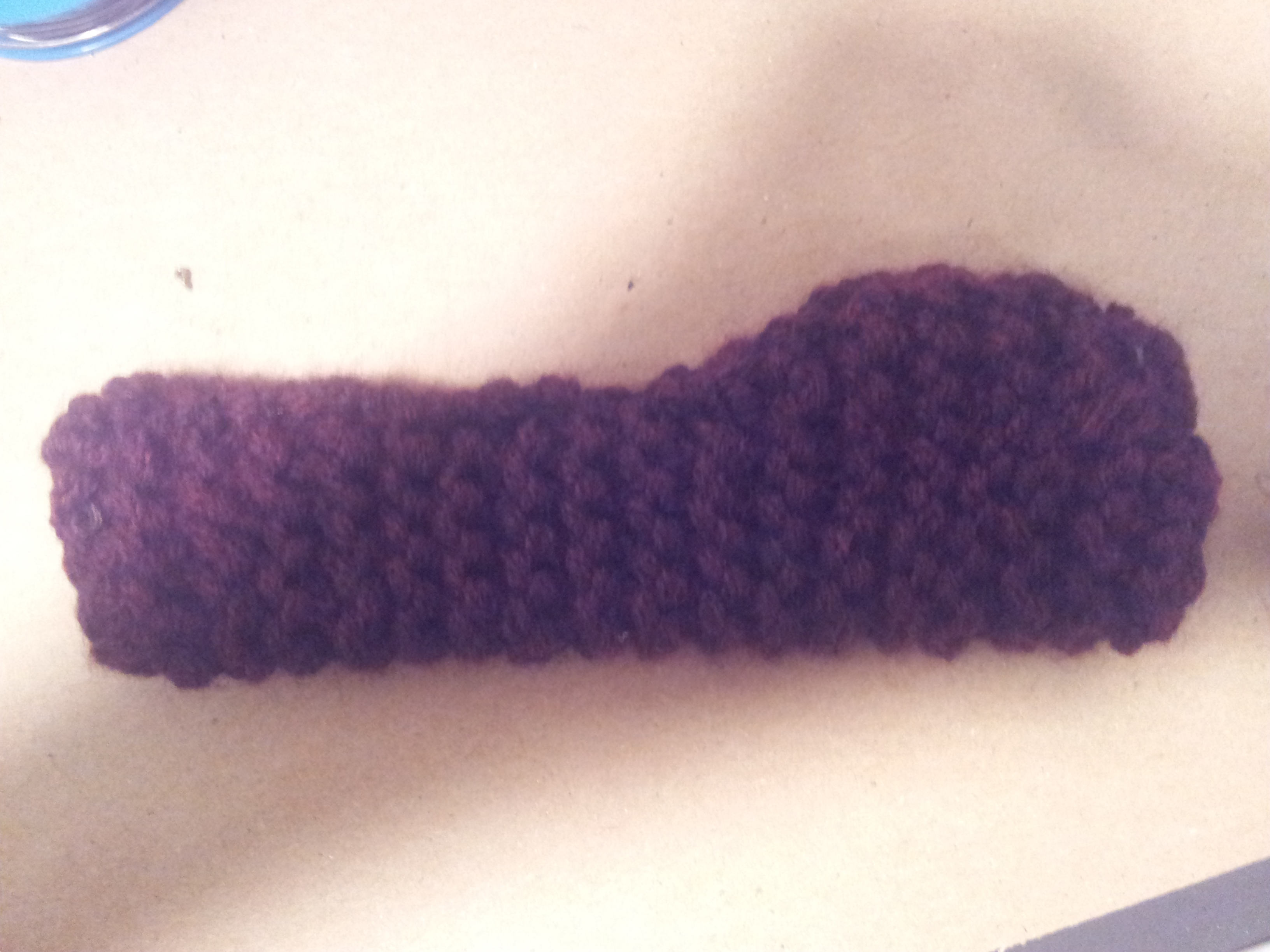
In case you want to try it, here’s what I did. I made forms that somewhat matched the shapes of my pieces, if my pieces were mirrored, because I planned to fold them over.
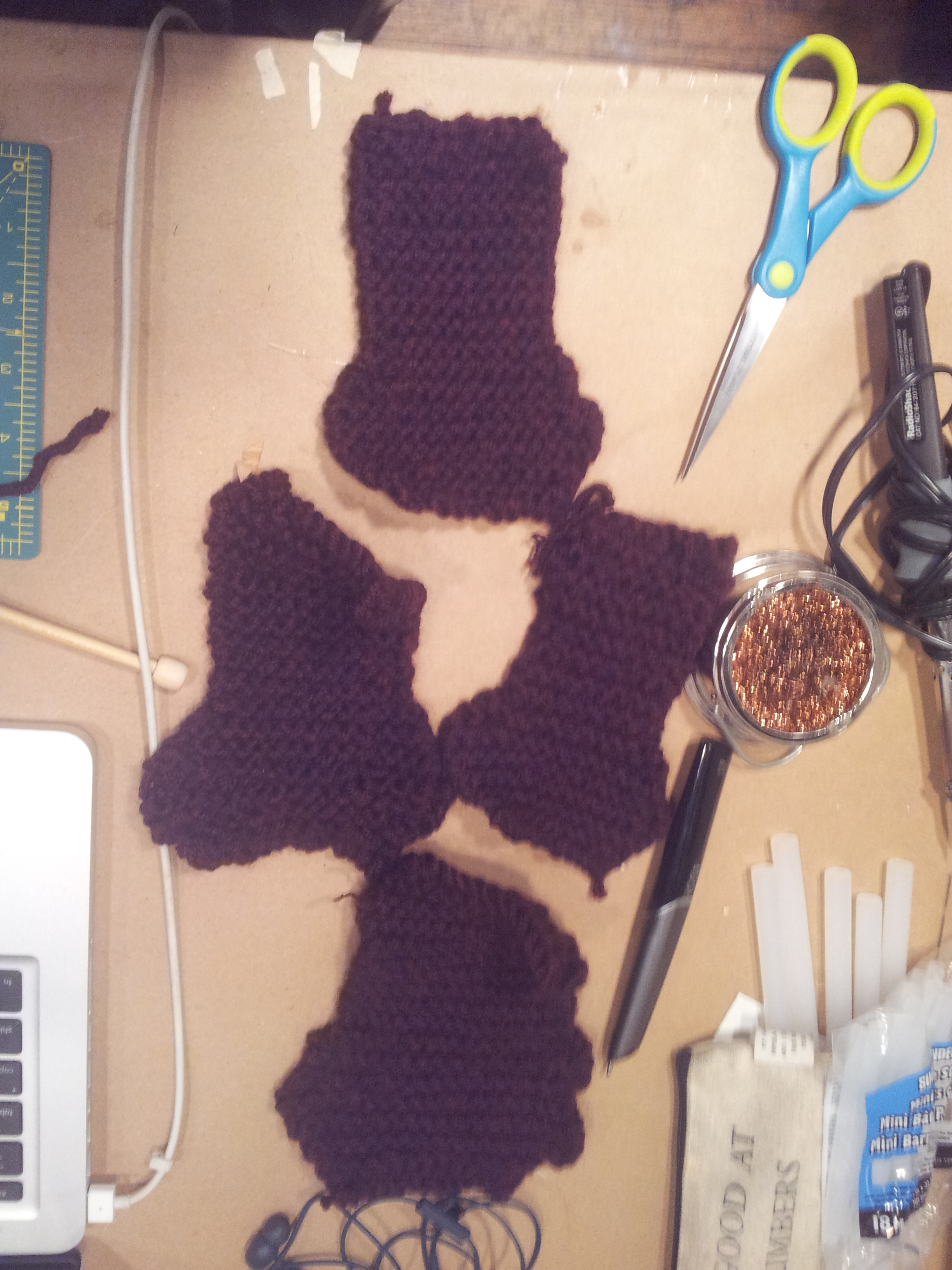
Not a perfect fit but the knitted yarn is stretchy and therefore very forgiving so I was able to pull it forward and sew it around the perimeter. I do wish I was someone who knew how to make knitting patterns and also properly knit, but I’m not! If you are, please tell me how to do this better.
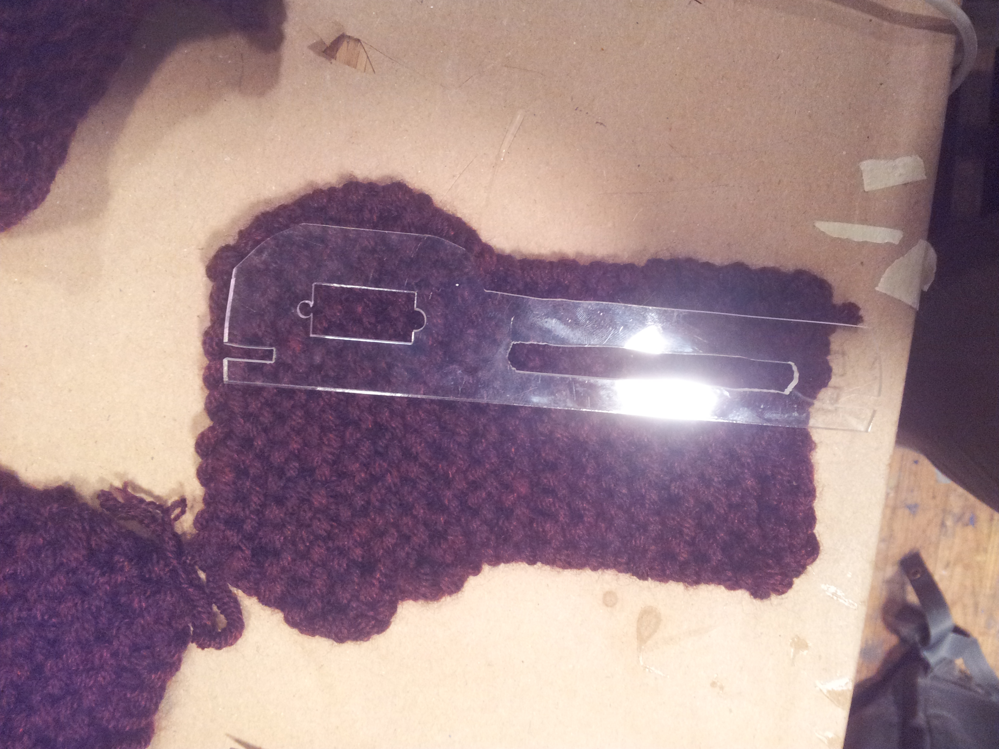
It looked pretty nice all closed up except for one major problem.. I needed the large slot cut out for the rod to pass through, as well as holes for my motors.
So from here on out I don’t know if I can call it a tutorial so much as a… documentation of my sort of haphazard technique, but I’ll show you anyway.
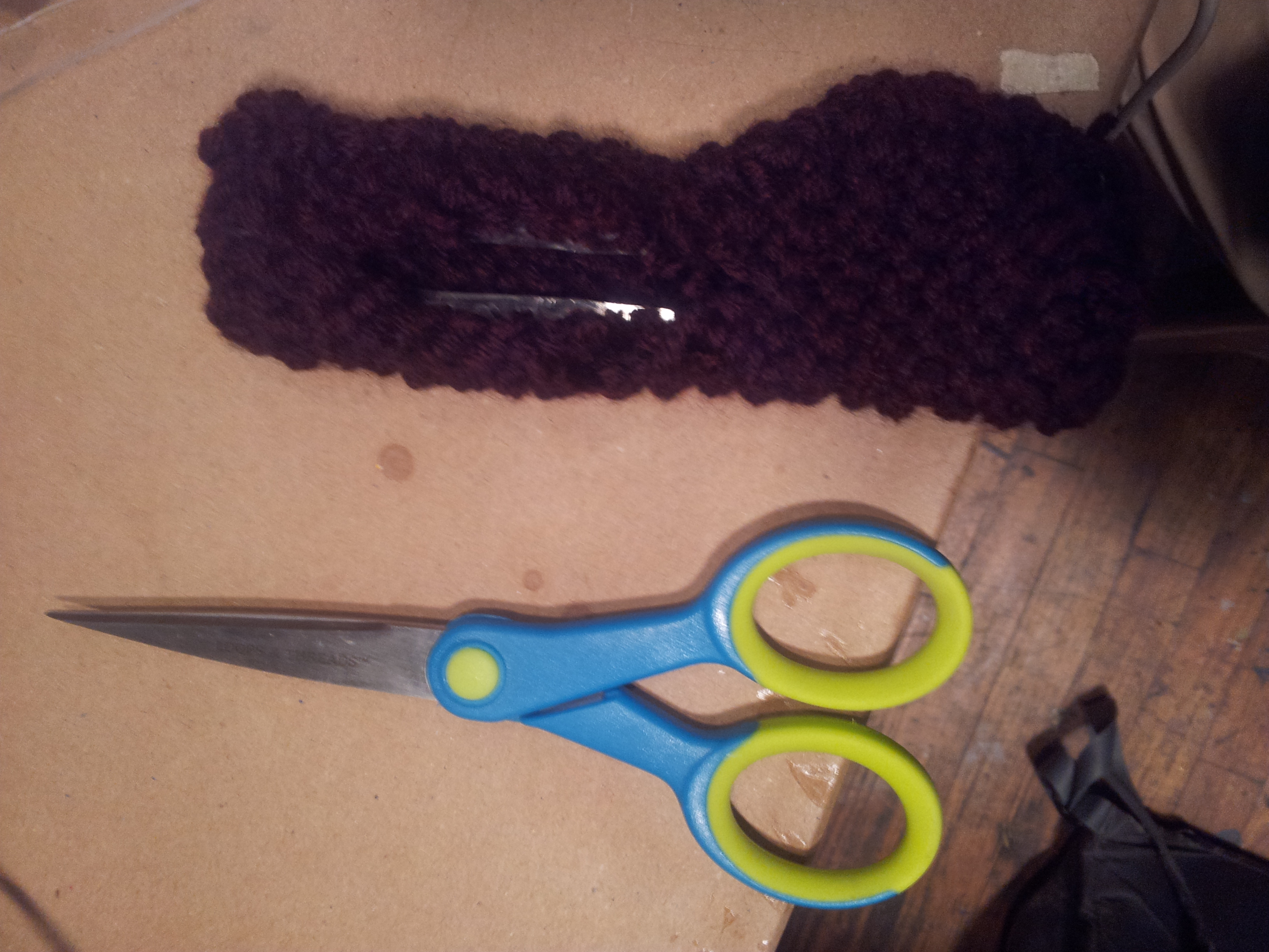
I cut holes in my knitting where I needed them and then I tried to carefully super glue the cut edges to the plastic, to prevent the whole thing form unraveling. It worked but it was messy and not pretty. I wish I knit the thing with the hole built into it, but that would require some actual knitting skills

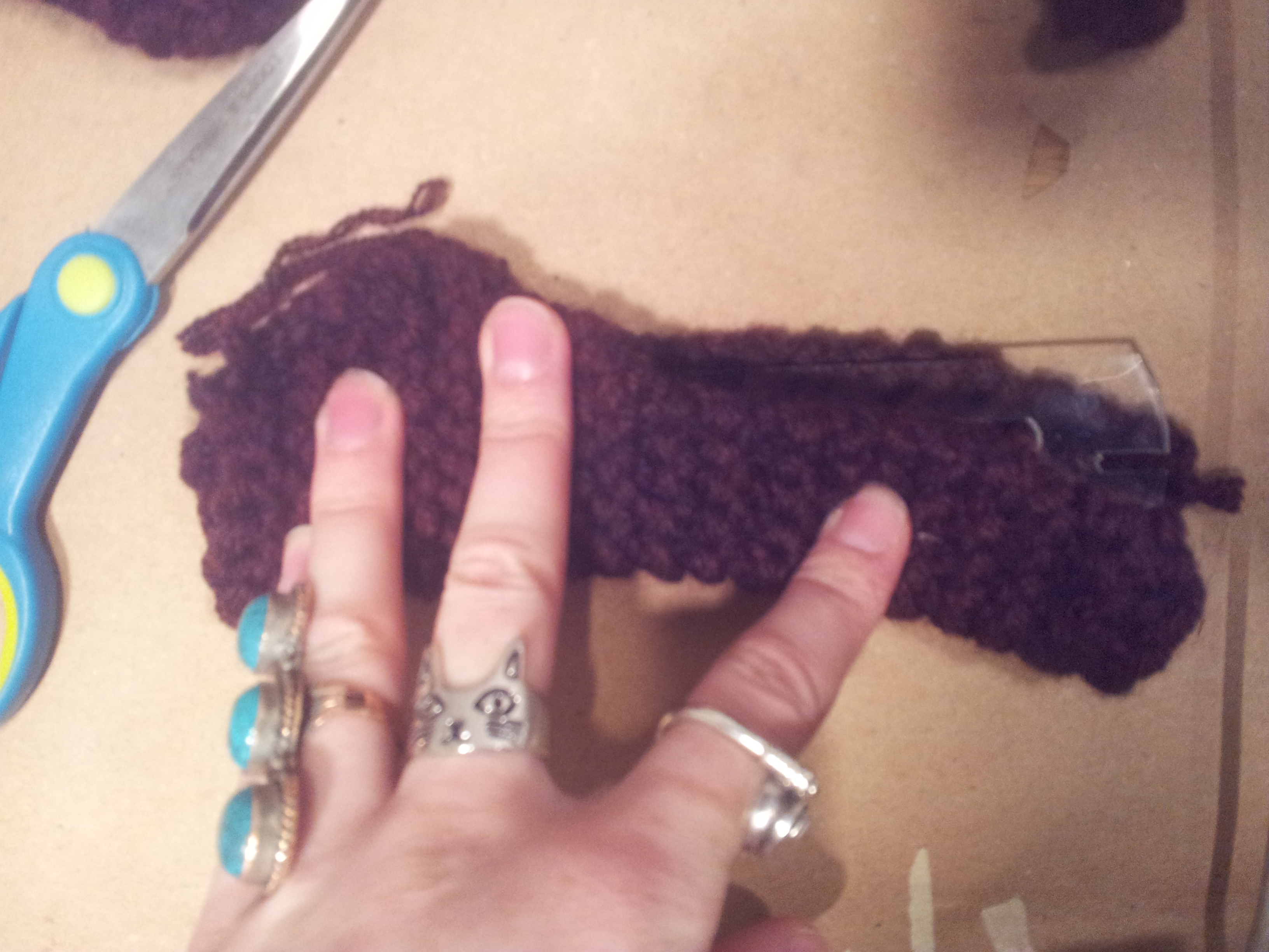
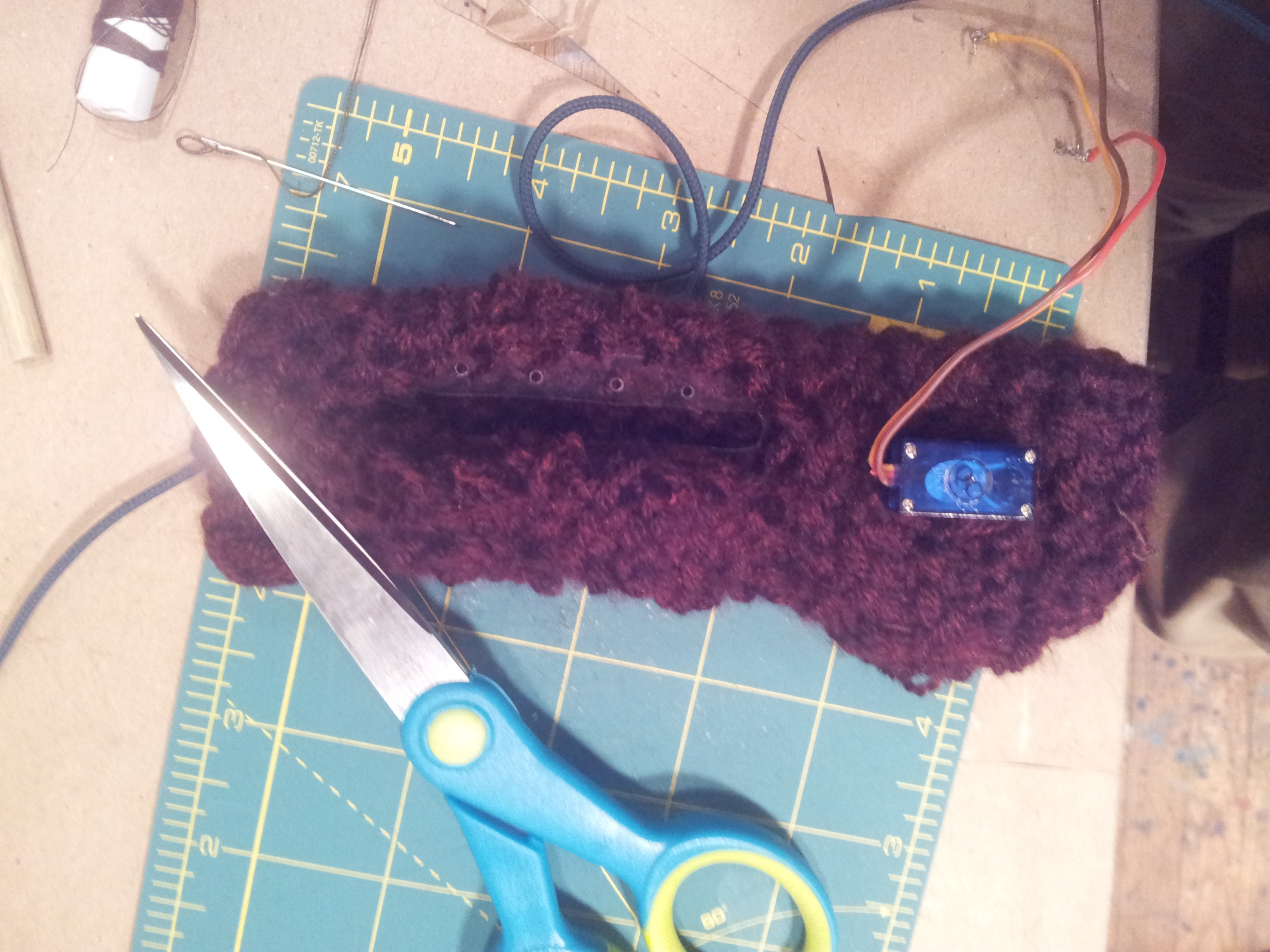
There it is all glued and I also sewed through it, because I had drilled those tiny holes around the perimeter, if you recall (pic below). Be sure to stick your dowel through and make sure it can still move, don’t get the glue on the edges because it will create friction. If you do, you can run a blade across to knock the dried glue off.

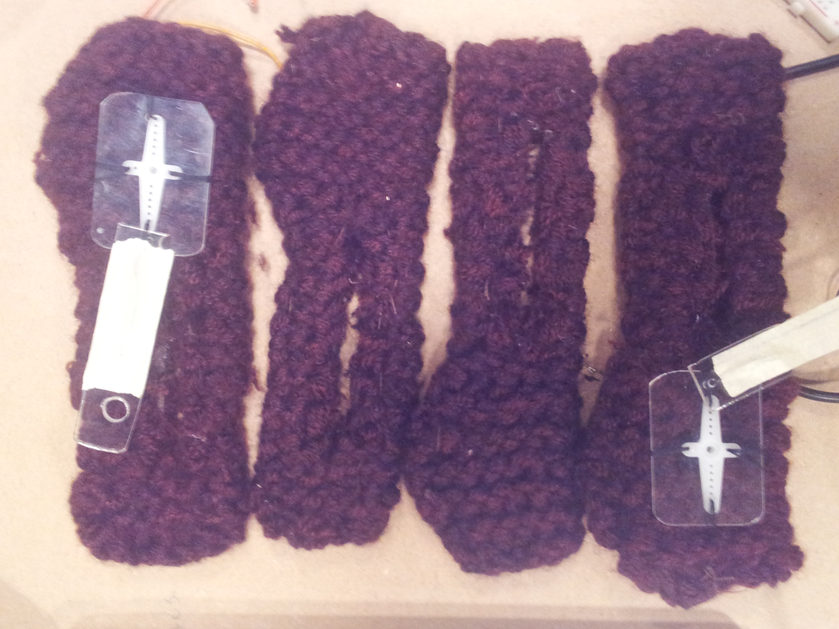
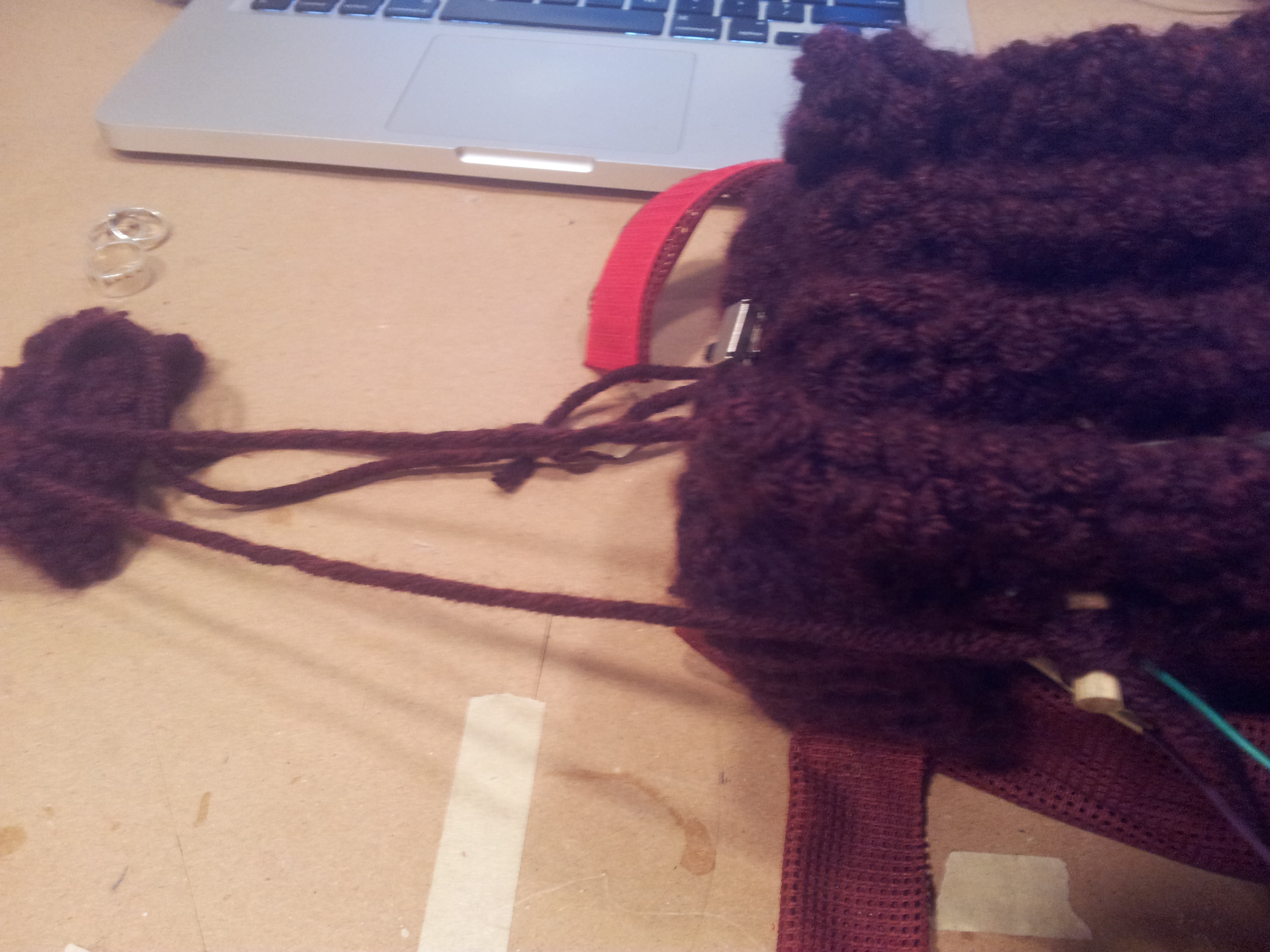
Here they are all finished! I used a similar technique to cover the base pieces, but unfortunately, didn’t document that. It’s much easier though, because you don’t need to cut holes. If you’re observant you may be thinking, ‘what about the slots?!’ My yarn was stretchy enough that I could just push it out of the way to fit the structure together.
If the structure doesn’t want to stay together, simply a run a piece of wire under it pull the base pieces toward each other. You can see my wire here:
The wire is black and running through the middle. (This is sturdy, coated steal wire, not the threaded wire for soldering)
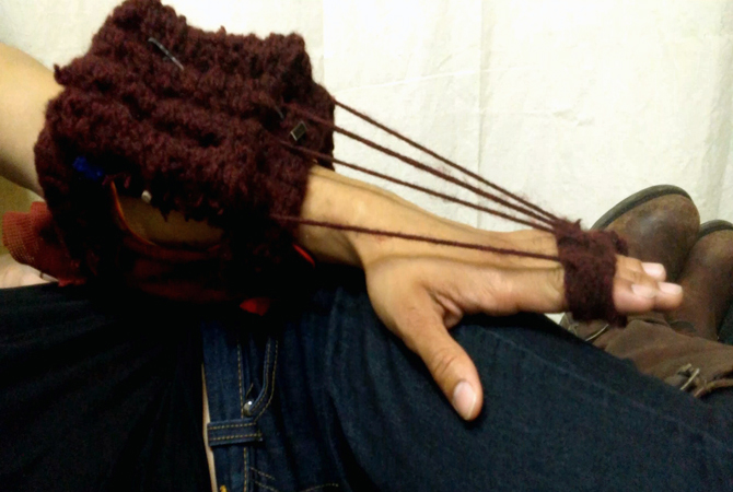
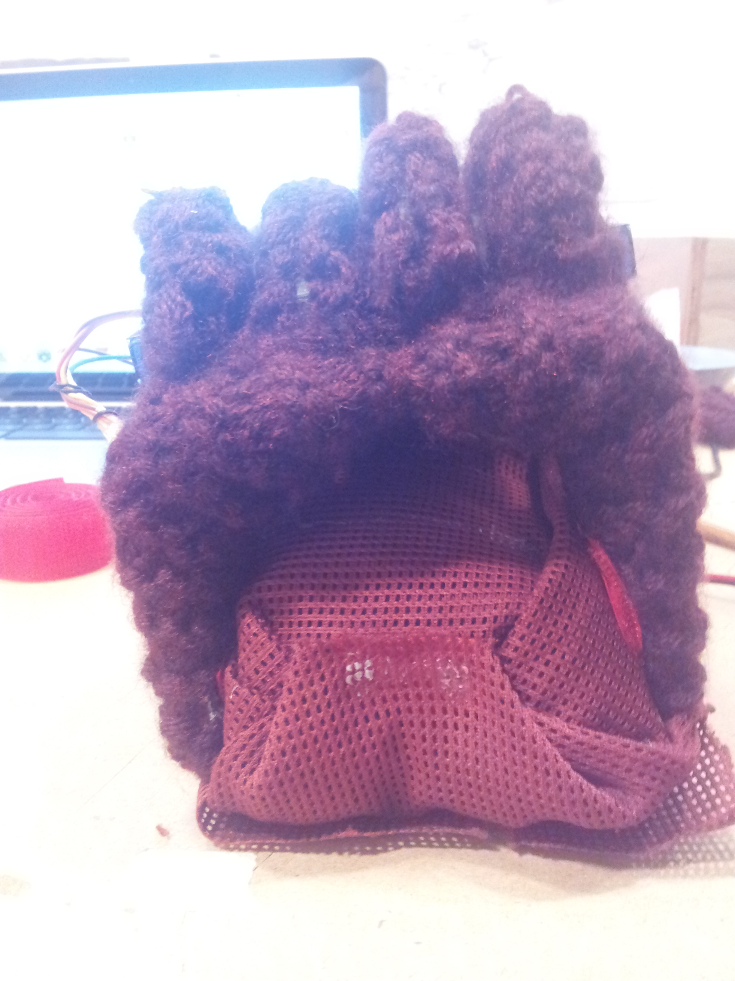
So there it is all assembled. I also knit the finger piece, but you could alternatively cut off the top part of a glove.
The strings are attached to the rod. You’ll want to try it on to get the length of the strings right, you need them very taut when the hand is at rest.
You may be wondering where the Arduino went. I decided to let my electronics rest under the arm. In order to do this safely you need to stack them carefully, and cover any exposed wires or solder joints so they don’t touch.
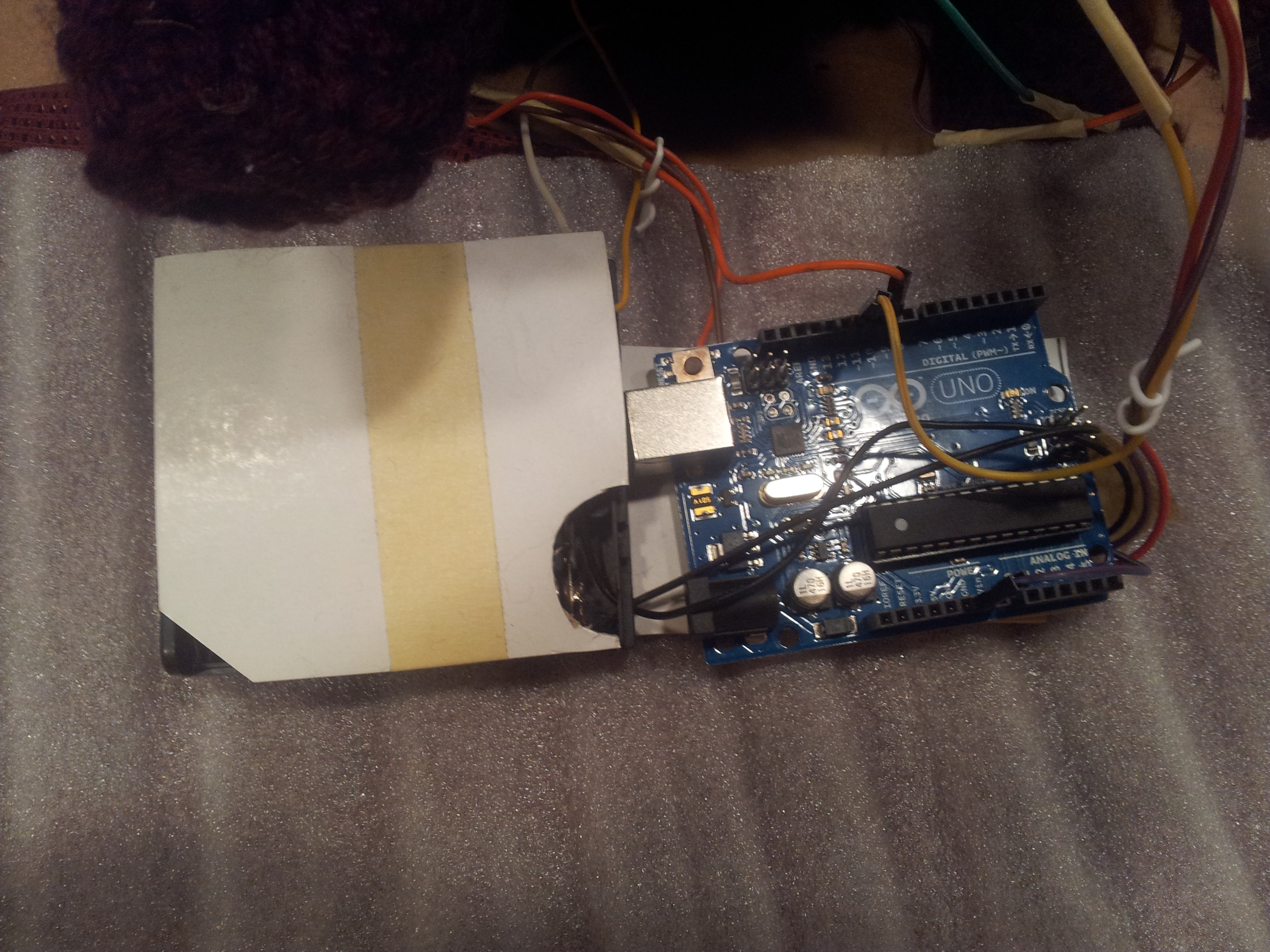
Piece of cardstock over my battery pack because the top cover broke off.
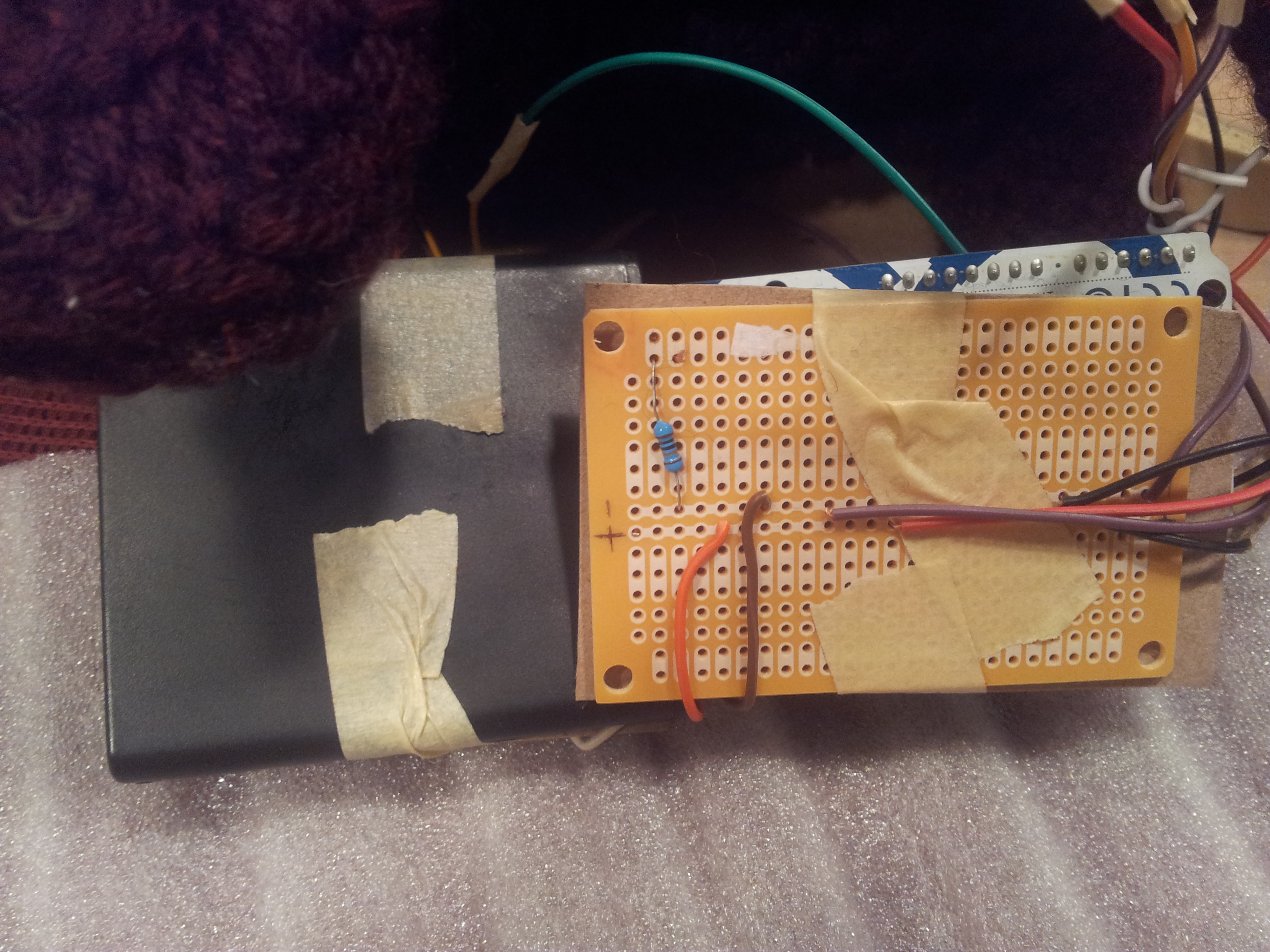
My PCB with is taped to the back of the Arduino, notice that piece of brown cardboard between them, so the metal bits don’t touch.
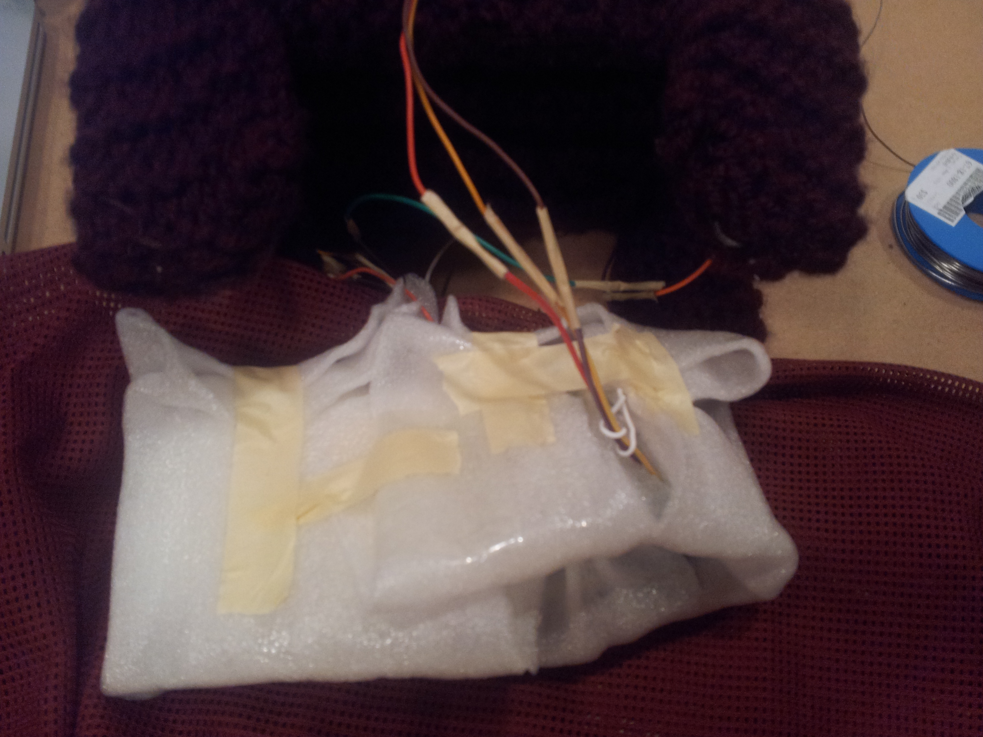
Then I wrapped it in thin packing foam to protect the electronics, and the arm from any sharp parts.
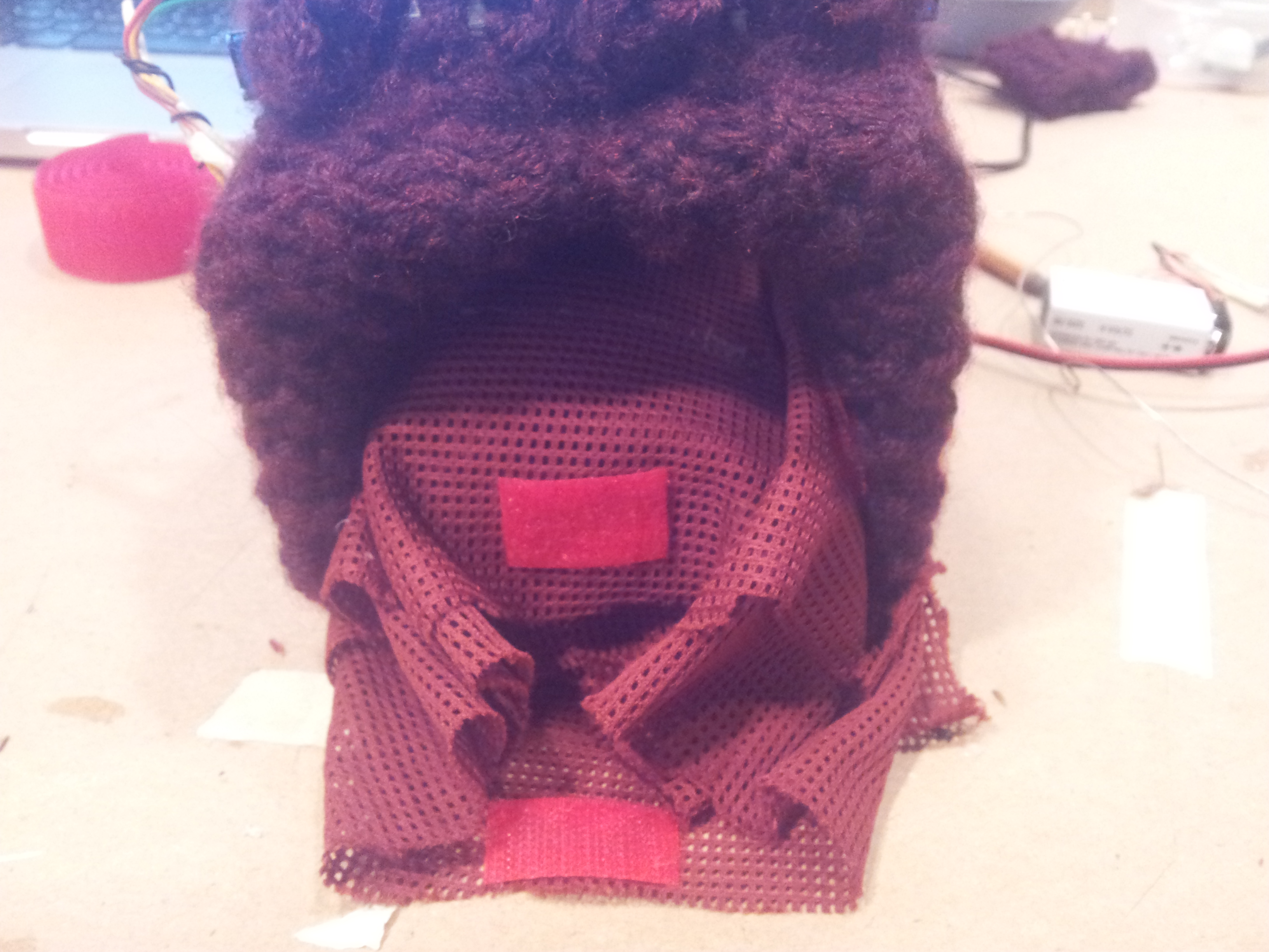
Next, I wrapped the little bundle of electronics in matching fabric. I added velcro and folded it up like a package. I didn’t want to sew it or do any kind of permanent closure that would make it hard to access the electronics.
The whole package is also velcro-ed to the sides of the arms of the bases. I definitely could of done it a bit lower, you can see my opening for the arm is a bit tight, my male model had to suffer a bit. (Thanks Kyle and Maren! Both wonderful painters.)
Lastly I added more velcro to the outside of the base arms, as a way of strapping it on more tightly.
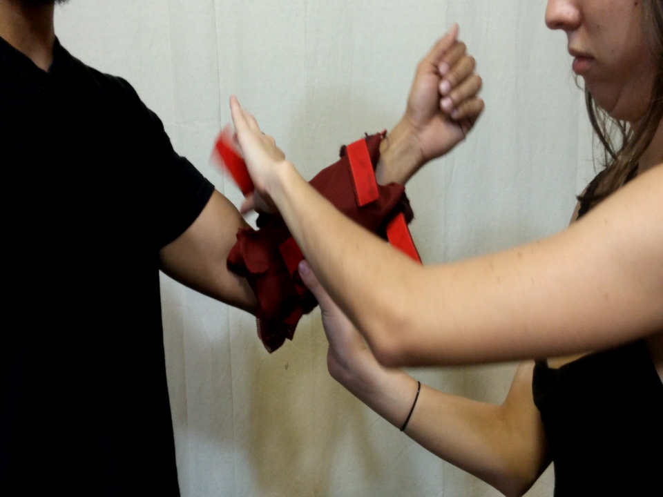
That was pretty key because you don’t want the machine slipping at all. It will try to slip because it’s easier for the machine to move than for his hand to move. Muscle resistance is a powerful thing! You have to strap them in nice and tight and it will hurt a bit. Love hurts. This concludes the Heavy Petter Tutorial, good luck!
