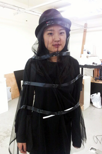
Miss-My-Face is a hat and veil lined with infrared lights that help protect your identity from CCTV footage. The device can be turned on directly with a button, or you can use a CCTV detector to turn the lights on automatically, when CCTV is detected.

Difficulty Level: Easy/Intermediate
Contents:
Supplies
-Electronics
-Garment
Step 1: Test LEDs
Step 2: Pin LEDs to veil
Step 3: Sew Your Leds
Step 4: Wire your LEDs and button
Step 5: Connect a CCTV detector
Step 6: Code
Comments Page.
(note: if you don’t know where to buy these things, check out the resources page)
-1 Arduino Uno
-4-8 meters super-bright infrared led strips. I bought mine here after speaking with the supplier, they recommended this one because it has 3 leds per square, so it’s very bright, and requires 12V. (some need 24V, you don’t want to carry around a 24V battery pack.)
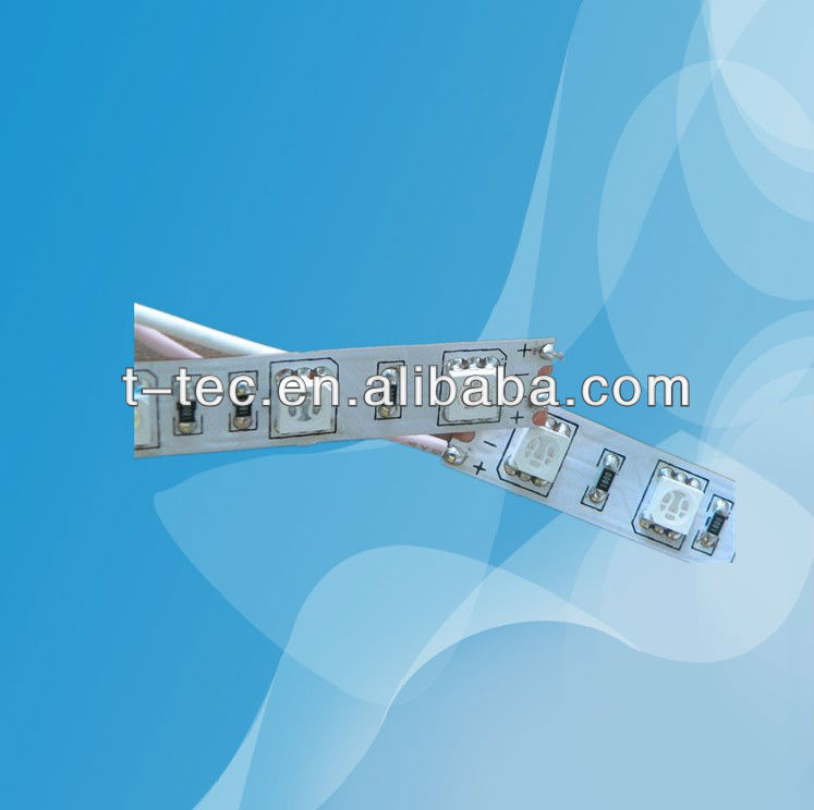
If you buy from Alibaba, or other wholesale supplier sites, you can usually request a sample for a cheaper price. 😉
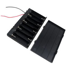
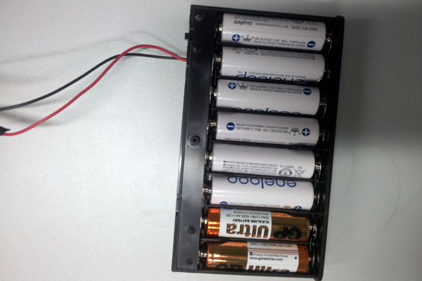
-1 battery pack that can hold 8 AA batteries, to give 12 Volts.
 x 1
x 1
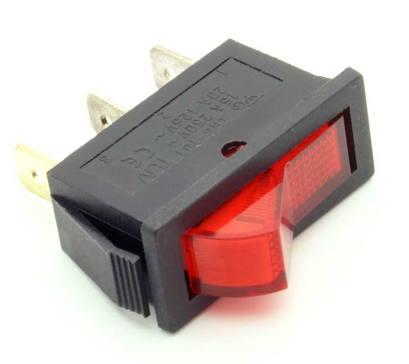
-2 on/off switches
 X 2
X 2
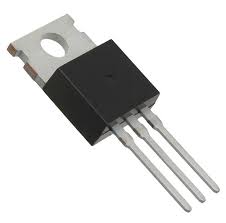
-1 NPN transistor, I used an IRF 510 as an alternative because I had it on hand.
 x 1
x 1
-2 100k resistors
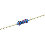 x 2
x 2
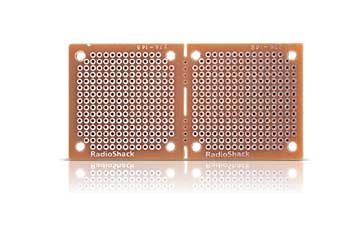
– 3 small pieces of blank pcb board for soldering
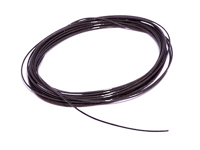
-Extra long wires for soldering, I used black to match my veil. *fashion*
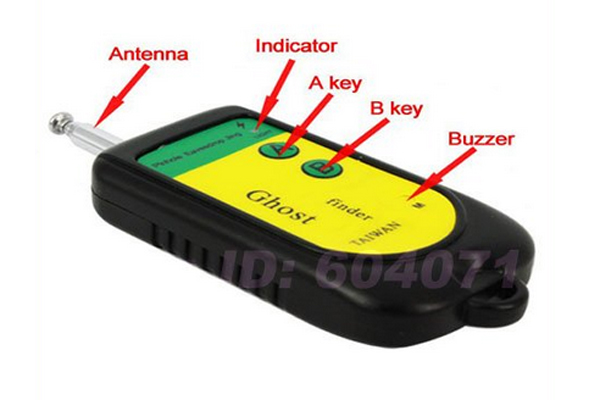
-1 CCTV Detector, I used this one which is cheap. Not the best quality but pretty good. It’s marketed as ghost detector (hehe) but it detects radio waves.
The following supplies are optional, I will go into more detail below, but these were what I used to communicate with Arduino when my CCTV detector got a reading, you may come up with a different plan, or skip the detector and just turn in on when you see a camera:
-1 Photocell resistor (senses light)
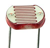 x 1
x 1
-1 small light proof box with a removable lid.
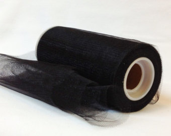
– 2 meters of tulle, or other transparent fabric in the color of your choice.
-3-4 meters of ribbon, 1 inch thick. (thick enough to cover led strips with extra room to sew).

-A hat or headband to secure your veil to. I thought the hat looked cool, and potentially you could store electronics in there, but I stored mine in the accompanying purse.

-A small purse you can keep with the set. I made a simple drawstring bag, which I’ll explain below.
-Sewing supplies. (pins, needle, thread).
Back to Top
-You’ll want to test the leds to make sure they seem bright enough before going through the trouble of sewing and soldering.
-For the test, you just need to connect your leds to a battery pack. Connect the ground wire of your led, to the ground on your battery pack (usually black but the ground on my led is white), and the red power wire to the red wire on your battery pack.
-Make sure you use the right voltage, my leds take 12V, so I connected 8 AA batteries. When it is plugged, you likely won’t be able to see anything with your naked eye, but trying turning off all the lights. In a dark room you can usually see a faint red glow coming from your leds.
-To check how the leds show up on CCTV, you need access to a CCTV monitor. Scope out your neighborhood, you should be able to see yourself in a monitor in some shops, metros, or apartment complexes. Hold the leds in front of your face and look into the camera. Have a friend check the monitor, does it look bright enough to block your face?
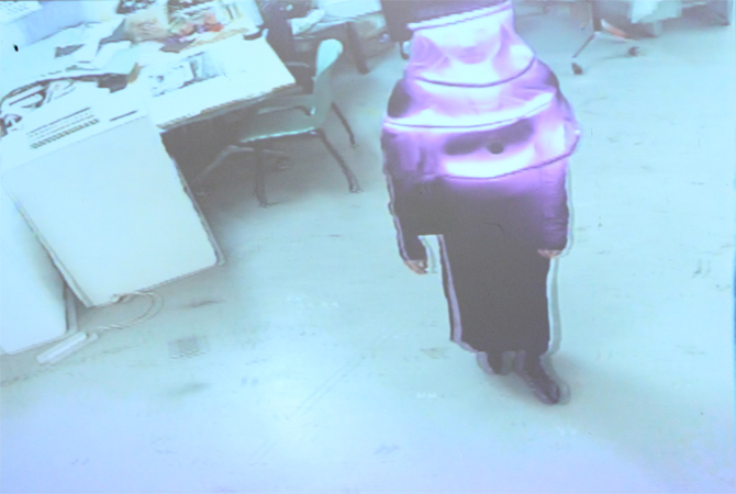
day light
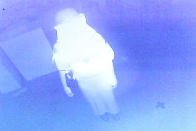
dark room
-Not working? Check a few other cameras, some very expensive CCTV cameras are capable of blocking excess light, but it works on most CCTV cameras. Also, remember that it works best in low light situations. Remember, it won’t show up on a regular phone camera or digital camera, you need to find a CCTV camera.
If it still doesn’t work, email your supplier and see if they have some brighter infrareds for you.
If you’re happy with the brightness, disconnect the lights from the battery and start pinning:
As opposed to other tutorials, in which we start sewing last, in this project we will get your leds pinned into your veil before we finish the wiring. This is because it will make it easier to check the length of all your wires.
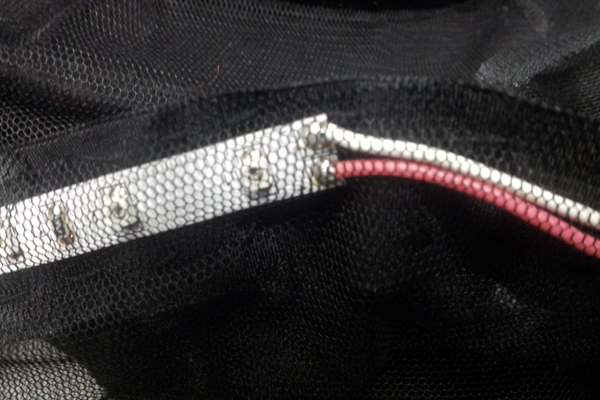
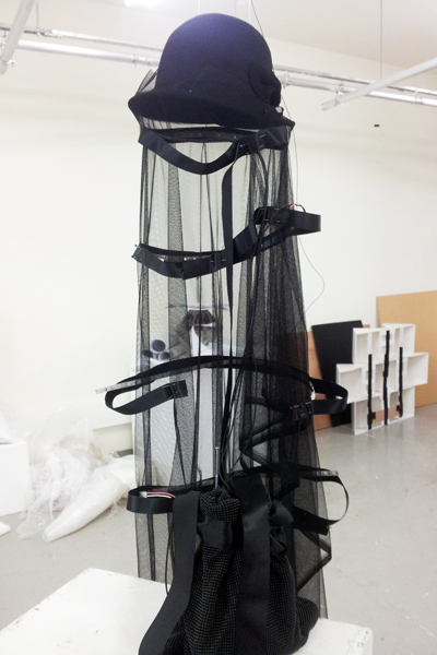
I cut a long piece of tulle and pinned it to my hat, then I pinned the leds along it, *facing inward*, by trapping them between a strand of ribbon and the tulle. When pinning, it’s helpful to have someone try it on, so you can get the placement of the leds close to the face. I should’ve moved my second strand of leds even higher for better blockage.
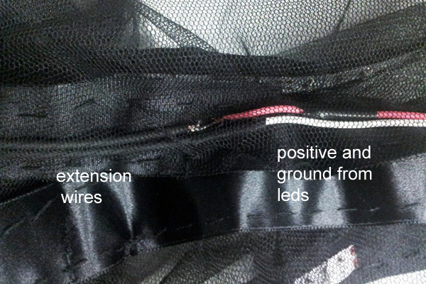
Once you have everything lined up, cut longer insulated wires, so that they can stretch down from the veil into the purse. (I hung my piece at this point to give my friend a break.) The leds closer to the head will need longer wires than those lower down.

Twist the longer wires and the wires that came on your leds, and solder them together. I labelled my positives and negatives with tape while I was working, because the longer wires are all one color.
At this point you can choose to finish wiring your leds, or to sew. Once your leds are wired, it might be hard to sew because they have a heavy battery pack attached, so you won’t be able to move the piece as freely. On the other hand, if you wire it all first, you can turn it all on and double check the placement before you sew.
I sewed first so I’m calling that Step 3.
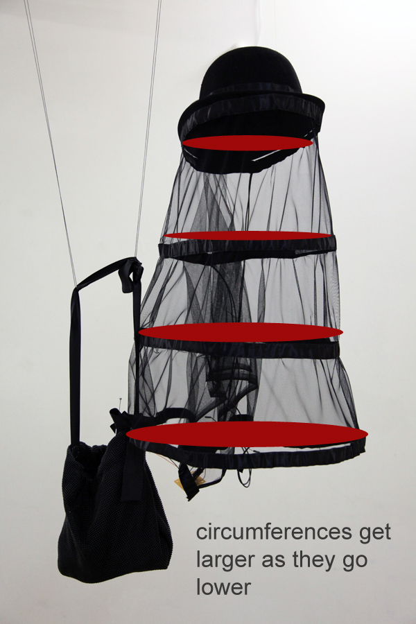
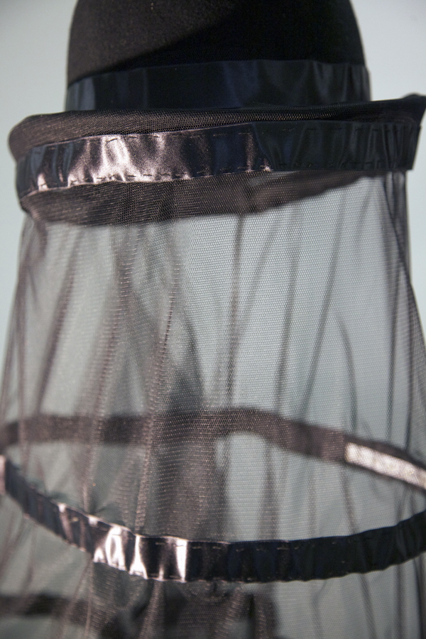
I did this by hand, it took a few hours, but I think it’s relaxing. Slowly stitch a line across the top and bottom of each ribbon, to trap the leds into place. This will also give the veil a rounder structure. If you think of the ribbons as creating circles, my circles got larger as they went down.
You can connect the circles at the back, or leave it open, to make it easier to put on.
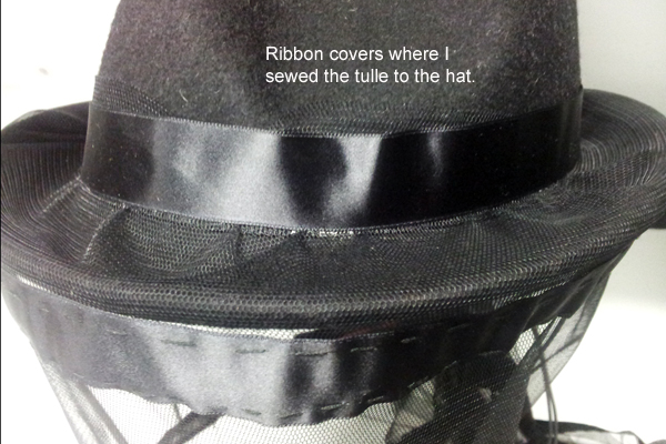
Lastly, sew or hot glue the tulle to the hat, and hide the edge with a ribbon.
Step 4: Wire your LEDs and Button
We are going to wire our LEDs to a transistor and a button, to allow the Arduino to turn them on and off. (We will add the CCTV detector last, optional).
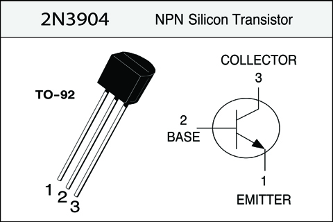
We are wiring the leds and the battery directly to the same pcb, but the transistor prevents the led from getting access to the batteries’ ground directly. The battery ground is connected to the “emitter” pin, while the led ground is connected to the “collector pin”. The base is connected to the Arduino through a 1k resisitor.
The Arduino will act like a “switch,” and allow the ground to flow between emitter and collector when we tell it to. **Careful**, the diagrams below are specific to an NPN transistor, if you use a different transistor such as a TIP120, that is fine but check the data-sheet because the Base pin may be the first pin rather than the second.
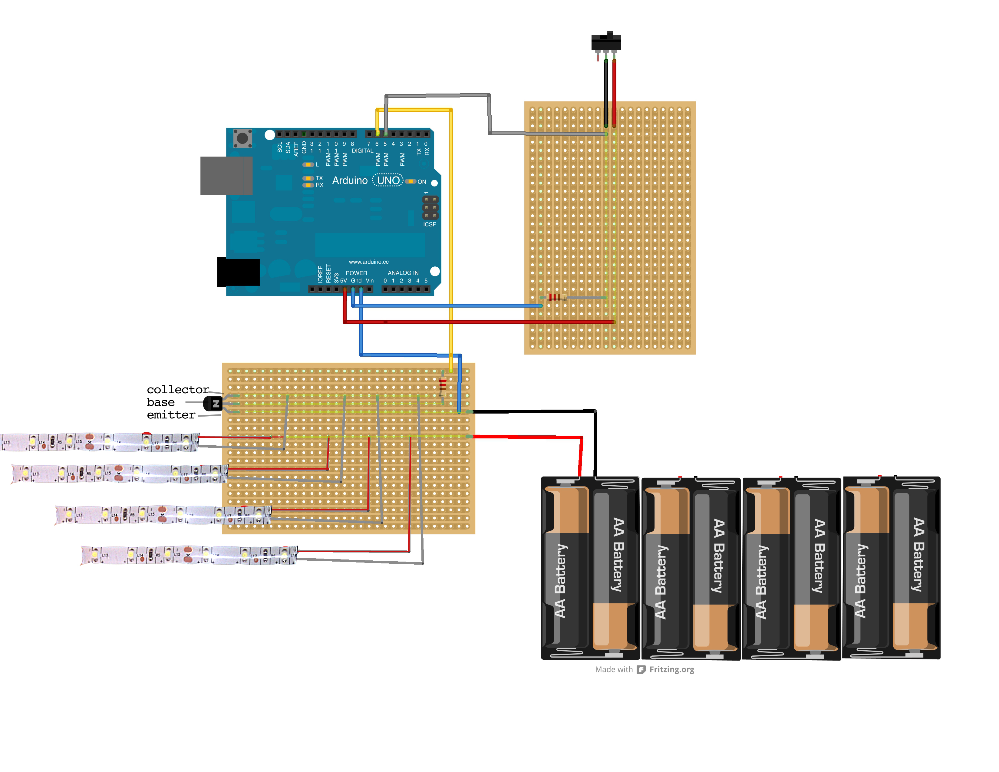
I used just one transistor for all my leds, because in total, I only used about 2 meters of leds. All of the grounds are connected to the Collector of the transistor, and all of the positives are connected directly to the batteries positive terminal. The ground of the battery is connected to the Emitter pin of the transistor, as well as to the ground of the Arduino. The Base of the transistor is connected through a 1k resistor, to the Arduino.
The on/off button is simpler, connect the middle pin through a 1k resistor to the ground on the Arduino. Also connect this pin to the Arduino. Connect the power to 5V on Arduino directly.
 <– the button is currently off.
The code for this is very simple, you will basically say,
if(buttonReading == HIGH) {
digitalWrite(ledPin, HIGH);
}
My exact code is in section 6, it also includes the code for the CCTV detector.
If you don’t want to add a CCTV detector, you can also just use your device as is, and turn on the device with the button whenever you feel like it. Test it on a breadboard first before soldering!
Back to Top
Step 5: Connect a CCTV Detector
So the concept of a CCTV detector is based on the fact that CCTV cameras are often far from a monitor, and so are transmitting footage to the monitor, using radio waves. My detector is looking for radio waves in the frequency of 100M-2.6GHZ, which is what most wireless cameras will use.
The detector won’t pick up any cameras which are closed, circuit which is why I added the above button, so that I could turn the device on directly too. Personally, I think I’d rather not leave it on all the time, wasting battery, so I like using the detector.
So, if you end up buying a CCTV detector it will probably be a bit different from mine, but I’ll show you how I “hacked” mine to communicate with Arduino, to give you some ideas.
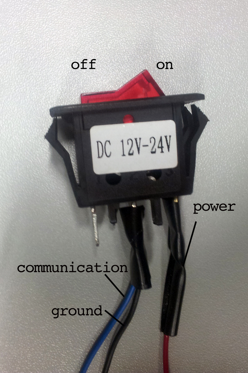
First thing is first, open it up. To turn on my detector, you have to hold down a button. I don’t want to hold the button down all the time so I connected an external on/off switch.
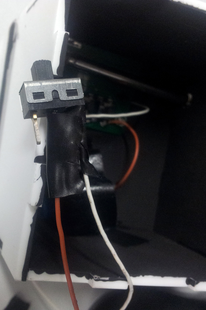
The power on the push button is connected to power on the switch, and the ground on the push button is connected to the ground on the switch. 2 wires, easy! In the picture, the switch is “off.”
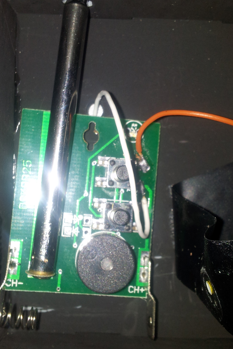
Now I can turn my detector on and off more easily. The second step is to figure out how to interface with the Arduino. My device has an led indicator light that turns on when radio waves are detected. I considered running a line from the led to the Arduino, because when the led is “high” I know I have a reading. In the end, this didn’t work the direct connection to the Arduino was giving my device a false positive.
Instead, I came up with a bit of a round-about solution. I made a little box and painted the inside black. I put my detector inside, and a photocell resistor. The photocell can detect light. When the led is off, it will get a low reading, because the inside of the box will be dark. When it is on, it will get a much higher reading.
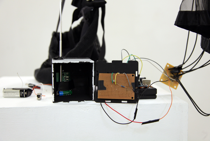
Here’s what that looked like:

Here’s my box, see the antenna coming out of my detector? The Arduino is sitting on top. The box is connected to the Arduino, and so is my LED transistor circuit. I didn’t give a picture of that close up because all the wires are black so it’s hard to see what’s happening.
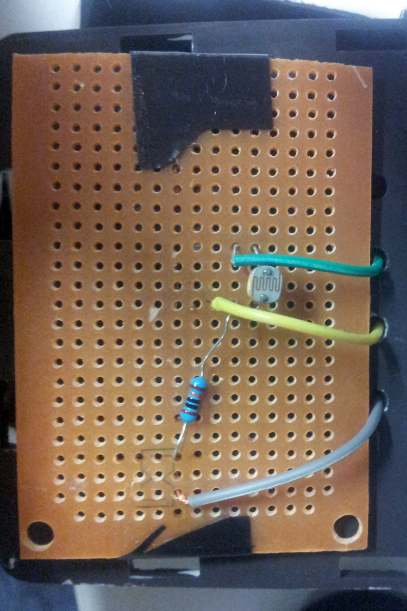
Inside my box, all black. We have my photocell circuit taped to one wall, and the CCTV detector against the far wall.
The photocell is simple, just connect one leg to positive, one leg to ground, and also connect the ground to the Arduino, through a 10K resistor.
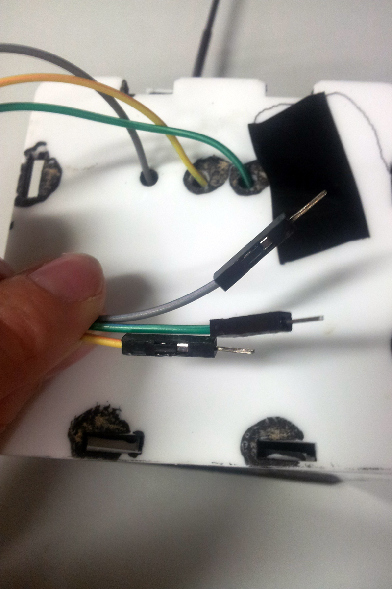
Out come my wires! Green is headed to power on the Arduino, Yellow is headed to ground, and Grey is going to Analog 0. If I want to unplug this box and use the Button we added earlier to turn it on instead it’s easy, I just unplug these three wires.
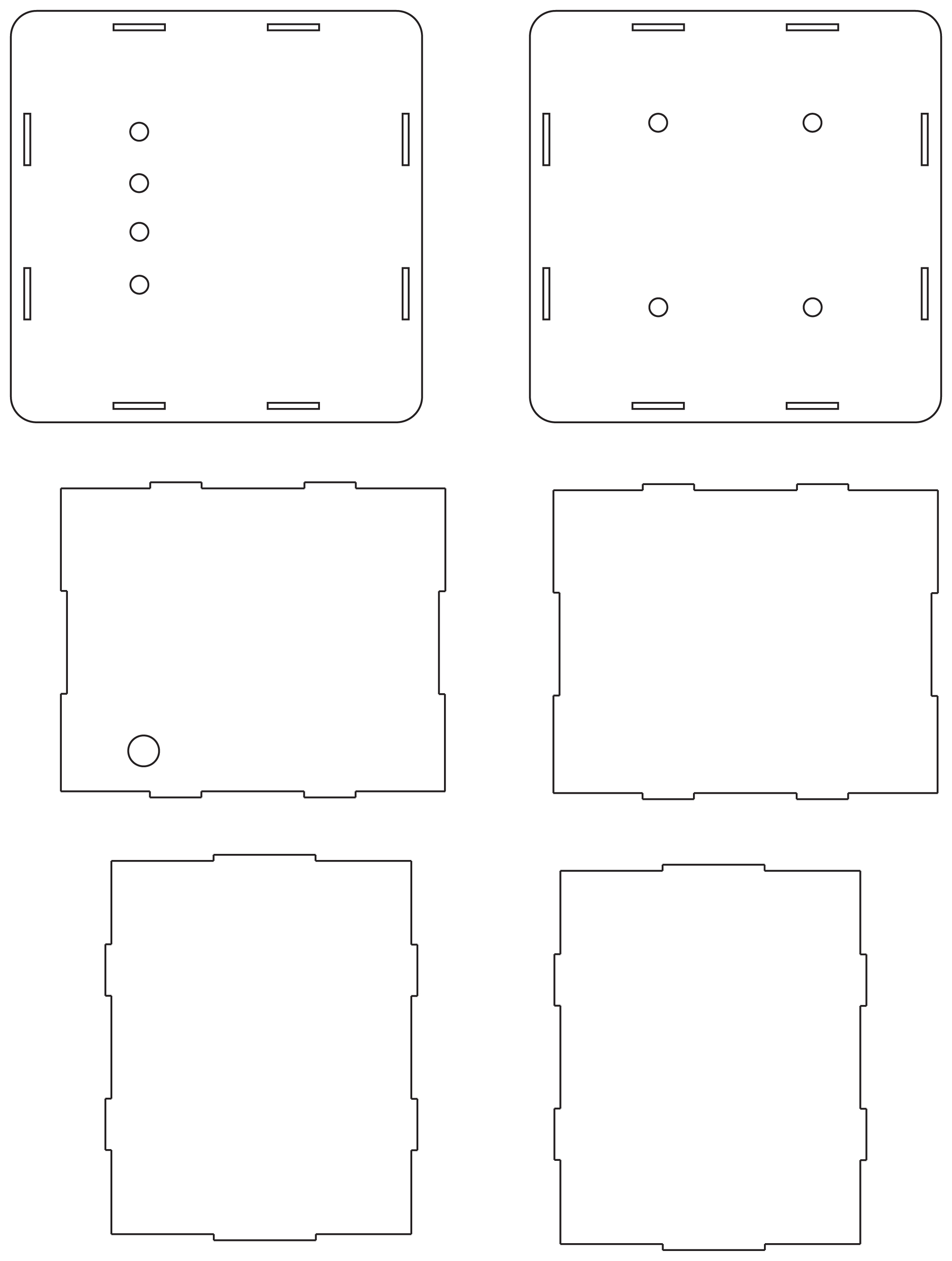
You may be wondering how I made this convenient little box. I laser cut the pieces! I had access to a laser cutter at the University I was at and my attitude was basically, “why not laser cut it?”. You can use my file as a reference if you have access to a laser cutter, but you need to adjust the size of the rectangle holes based on the thickness of your material.
Download the AI file here
There are two inputs, the button we wired in Part 4, and the photocell reader. I usually only have one or the other plugged in at a time, but if both are in the code it means I don’t need to upload any new code to my Arduino.
There are two LEDs listed, one is correlating to the infrared led strips, one is correlating to the Arduino’s onboard led. I use this for troubleshooting, because it’s easier to than finding a CCTV camera.
For the photocell, because I want to compare the light levels inside my box, I look for a difference in light levels between each sensor reading. This is why I have a photocellReading and photocelLast. I experimented while plugged into my computer, so I could read the serial monitor, and found that a difference between readings greater than 15, meant my cctv detector’s indicator light was on.
#include <Servo.h>


int photocellPin = 0;

// the cell and 10K pulldown are connected to a0

int photocellReading;

// the analog reading from the sensor divider

int photocelLast;

int LED = 7; //infrared led strips
int led2 = 13; //onboardled

int button = 6;

int buttonState= 0;

void setup(void) {

// We'll send debugging information via the Serial
  Serial.begin(9600);
  pinMode(LED, OUTPUT);
  pinMode(button, INPUT);
}

void loop(void) {
  photocellReading = analogRead(photocellPin);

  Serial.print("Analog reading = ");
  Serial.println(photocellReading);

// the raw analog reading
// that means we have to invert the reading from 0-1023 back to 1023-0

  photocellReading = 1023 - photocellReading;
  buttonState=digitalRead(button);

 Serial.println(photocellReading);

if((photocelLast- photocellReading) >= 15) {
   Serial.println("Difference! CCTV?");
   digitalWrite(LED, HIGH);
   digitalWrite(led2, HIGH);
   delay(5000);
 }

else{
  digitalWrite(LED, LOW);
  digitalWrite(led2, LOW);
 }

if(buttonState==HIGH){
   digitalWrite(LED, HIGH);
   digitalWrite(led2, HIGH);
   Serial.println("BUTTON");

 }

else{
 digitalWrite(LED, LOW);
 digitalWrite(led2, LOW);
 Serial.println("nobutton");
 }

photocelLast = photocellReading;
  delay(100);
}
And that’s pretty much it! I’m no expert at this stuff, so if you find a better way to do something, or you have some questions or comments, please share them on the comments page. Also, please do send a photo if you make one for yourself :).
