CinnaBrooch consists of a homemade mechanical leaf shutter, a cinnamon bun, and a moisture sensor. The moisture sensor rests inside the armpit. When you are nervous and perspiring, the shutter will begin to open and close. The alluring aroma of cinnamon buns will then waft over all in your vicinity.
Difficulty level: Intermediate/ Easy
(The electronics are pretty simple! The structure is the hard part here, access to hand tools is a must; laser cutter not strictly necessary but it’s a big help)
Supplies
1.Design
2.Make the Structure
i.Top
ii.Bottom
3. Wire the Circuit
4.Code and Test
I should probably make this the first step of all my tutorials! It’s rare to have an idea, draw out a design, and achieve it the first time. I don’t always document the failures well. But happen to have pictures of this one. This first version of the Cinnabrooch, I thought I could poke holes in an enclosure and spin a fan around to waft the cinnamon smell out. (left two pics).


While that design did allow for a gloriously massive cinnamon bun, it didn’t really do a good job wafting the odor out. I realized I needed a much bigger hole to let the air out and then I needed that much bigger hole to open and close, and so that’s why I ended up making something more like a mechanical leaf shutter.
Your design will no doubt change as you start working, but it’s always good to think about where you want it to go on your body, how you’re going to package everything, and how you want it to look in the end. I used clear acrylic for the shutter, so you can always see the bun, and that decision dictated a lot of my other decisions.
Back to Top
Some of my projects are more challenging on the electronics end, that’s not the case for this one. The hardware is pretty straightforward, it’s the structure that’s tricky here.
First of all, this is the tutorial I followed to make my version of the leaf shutter, I had to modify it somewhat to make it work with the acrylic and of course had to automate it. But I think their shutter is much prettier than mine!! And more functional, because they used a flatter material, the metal.
http://www.instructables.com/id/How-to-make-a-12-leaves-Mechanical-Irirs/
So my decision to use acrylic is what made my shutter a little more difficult to pull-off, because it’s a material that is not as thin as sheet metal. But like I said, I really wanted to it to be clear, so I got some 1/16 inch clear acrylic, and I laser cut it out using the file shared by Kommodore on Instructables. (Cutting the sheet metal by hand is easy, but acrylic is harder, would need a steady hand and a scroll saw, and I had neither at that time so I used a laser cutter.)
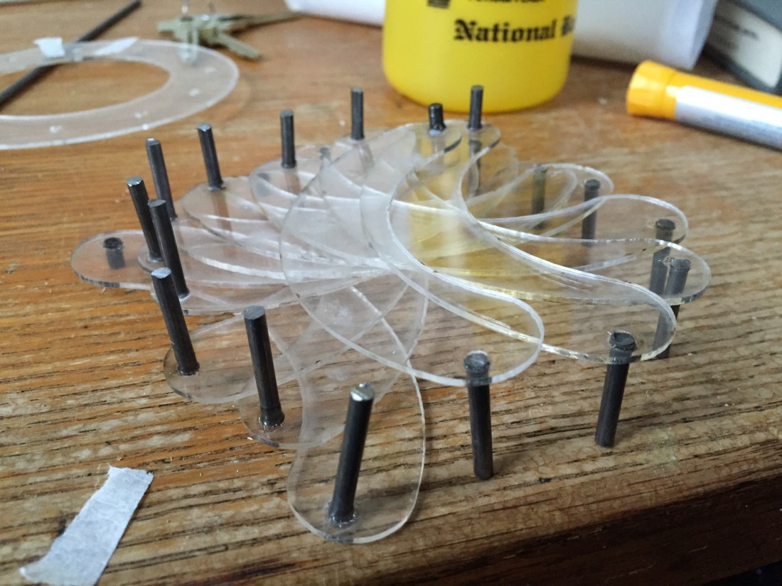
But what I found right off the bat was that since my material was thicker, it wasn’t going be able to lay flat, and therefore I needed different sized pins. Here’s what I mean:


The little “leaves” need to pass over the top of each other for this whole thing to open and close. The acrylic leaves are too thick, so I had to kind of stack them up. So instead of using the pins from bike chain suggested by Kommodore (which is a great idea) I cut down descending pieces from a steel rod on a chop saw.

Tried to get two versions of each size, but wasn’t as precise as I should have been.

I thought I might be able to laser cut a couple pieces of the base plate design and stack them but it was not deep enough to hold the lower pins (since my pins were getting so long). I think wood would have worked best, but I didn’t have access to a table saw or router at that time (recurring theme in this one, had just moved and did not have access to usual tools when I was trying to do this project!) so I found that foam worked pretty well:


The foam slots are basically keeping my rods on a track. The steel rods are increasing in size, because the leaves that are on top are also higher, and therefore further from the base. (This is not an issue if using a thinner material).
So the piece that will be on the bottom needs the shortest peg on the bottom side, and the longest peg on top side, because that would be the furtherest from the top piece. A little confusing, but I laid out my pieces one by one and super glued the rods in:
smallest / biggest
2nd smallest / 2nd biggest
and so on. Somewhere in the middle the rods were the same on both sides:
medium/ medium
and then it flipped and the last few pieces were:
2nd biggest / 2nd smallest
biggest /smallest
Example of biggest/ smallest:

I actually just did one side on all of them first to make it easier to see:

So that top most piece needs a rod pointing up, to be able to grab the top piece that we will add later. And since it is close to the top already, it will get a short rod.

Here it is before I switched to a foam base.
The top piece is a little hard to see on mine, because of my decision to use clear acrylic. but it is a disk with holes in it that keeps the top pins in place. 
This is Kommodore’s top piece, in white:
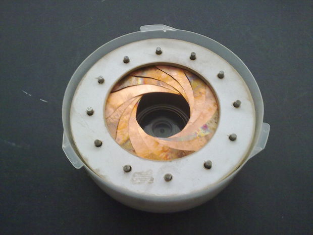
See how the pegs poke through it? Mine are doing the same thing but harder to see. And since the whole thing is deeper we also have some longer pegs.
You should be able to twist the top piece by hand to test your shutter at this point. One benefit to using foam as the base was that it was easy to make changes. Some of the longer pieces were dragging a little so I cut out the ridges deeper with a knife for those ones.


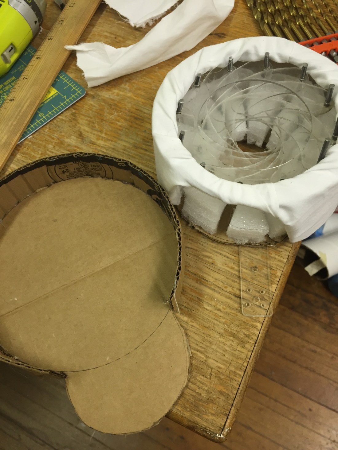
As you know by now, this was a mostly shop-free project. (Aside from the laser cutter and chop saw, which I was lucky to get access to). So I had a reel of RGB LEDS (from The Perfect Fit!) and I cut out the inside of that with combo of a knife and wire cutters, to get a nice rigid plastic circle.
I then cut out the same shape in cardboard and glued the plastic to that. Then I cut a long strip of cardboard and scored it vertically so that it could bend, and I bent that around the circle frame to make a wall and glued it into place. It’s pretty sturdy! I think it was an Amazon prime box.
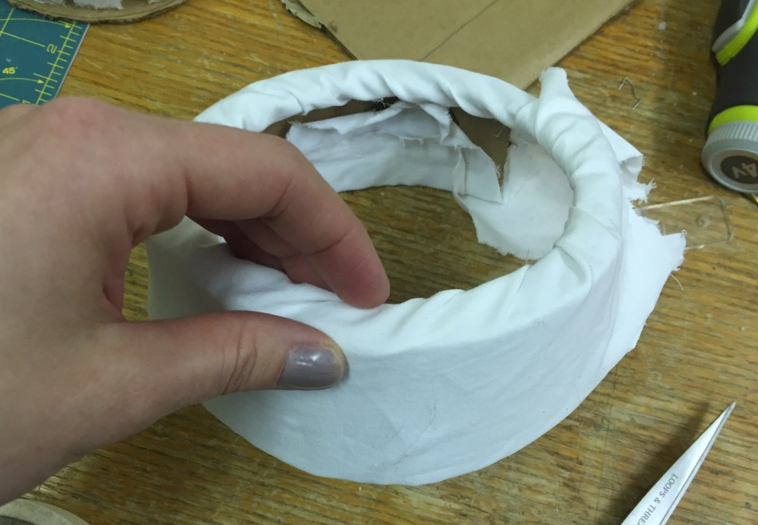
I covered the top with fabric at this point, in part because I was still trying to figure out if this method would work for the final form. You could wait and do the fabric or paint or whatever surface treatment, once the structure is done.
My first bottom piece was designed to have the motor and the shutter structure sit on the same piece. I ended up changing that because I decided to rotate the shutter from the bottom, so I needed the bottom circle to rotate freely, while the motor stayed stable.


So if you looked at the Instructable tutorial (which you should because it’s great) you’ll notice the creator opens and closes the shutter by rotating the top piece. That was my original plan too, but then I switched to controlling it from the bottom because I found when I was testing by hand that rotating from the bottom was more stable, and the structure was easier to hide on the garment.

So I ended up cutting that original base piece with the battery graphic on it, and making it into a donut and hot gluing the base foam to it. Again, my plan here was to rotate from the bottom of the shutter, as opposed to the top. So I hot glued an acrylic tab to the bottom, which I will control with a motor.
Then I made an additional structure to put the rotating base piece on.
Base piece on left. Cinnabrooch with rotatable base on right. See the clear acrylic tab coming off it.
If I really wanted to improve the function of this thing, I could have set the whole bottom of the brooch (right) on a greased pin, so it didn’t sit on the cardboard base (left piece) directly. That’d be good for version 3. In this iteration, we have two pieces of cardboard sitting on top of each other, and they will rub against each other as they spin, adding unnecessary resistance.

Here’s the shutter, with the acrylic tab coming off the bottom foam/cardboard, sitting inside the base piece. So the next challenge is to figure out to how to mount the motor in a stable way, to move this tab and rotate the whole base of the structure.
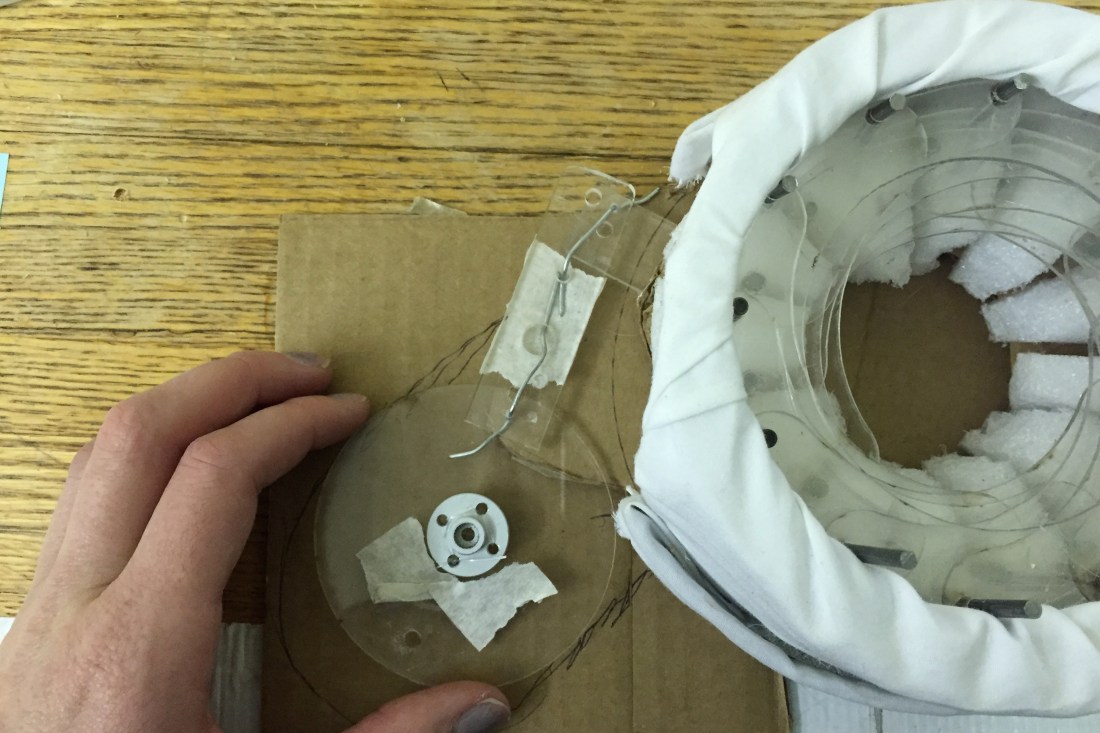
So because we are trying to move this tab in a small space, with a servo motor, we need some additional mechanics to extend the circular arc of my motor. (Side note, this is a similar problem to what I was solving with The Heavy Petter, also a no-shop-access project. Would be nice to fab both of these at a higher caliber, I’m sure the functionality would improve if the parts were machined. But we don’t always have access to a machine shop, in life.) So the circle piece rotates from 0-180, and then there’s a little wire pin (joint) connecting the circle to an arm, and there’s a pin (joint) between that arm and the tab of the shutter base.

So this top drawing can show position 0.
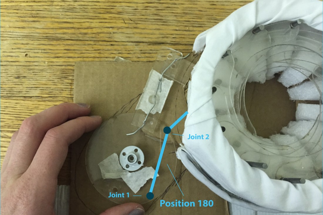 I always feel like I’m taking enough pictures, but it’s never enough. There’s no photo of how the arms move in the next position, but they would follow the blue lines. The two joints allow the arm to rotate, which lets us fit this system in a smaller space.
This video at 0:46 shows a similar principle:
It’s the kind of thing that makes sense as you do it. Cardboard and wire, or paper and paperclips as pins/joints are a good way to mock up and think about how things move.
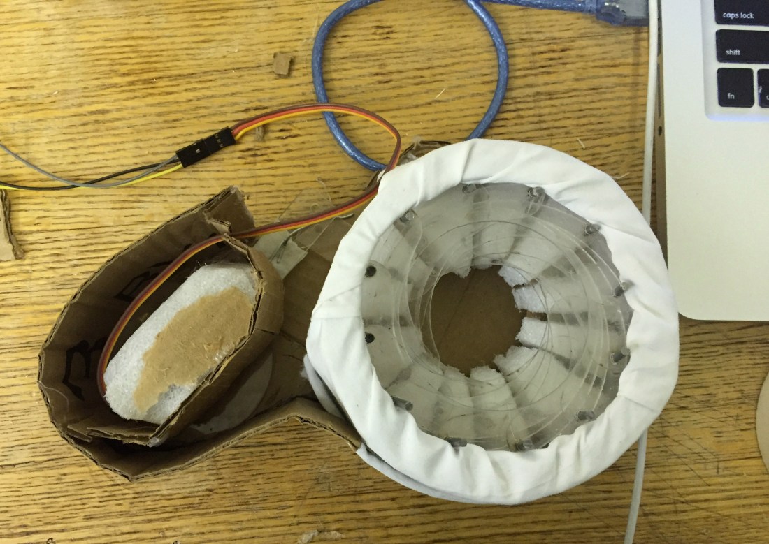
Then my motor clicks into place, and I stabilized it against the sides of the cardboard with hot glue and wire. You want the motor to stay as still/stable as possible. Some kind of laser cut acrylic structure would have also worked well to keep the motor stable.
At this point, if not sooner, you definitely want to see the motor moving and make sure structure works well before completely enclosing it.
The rule is always to test the parts of your circuit in isolation. So that means test the motor on a loop, before you test it with a sensor. Another rule, is when you are using a motor and a sensor in combination, you almost always want to power the motor from a separate power supply. Your motor may work ok running from your Arduino directly, but once it’s under a load (the mechanical stress of pushing that arm) it will draw power away from your sensor and you’ll get erratic values.
So, Step 1. Motor + External Batteries:
Step 2. Motor + External Batteries + Sensor:
5. Solder
Switch to a smaller microcontroller, and use header pins on a PCB.
Back to Top
