Urban Armor #7 consists of a dress with nine built-in mini fog machines. Using a GSR sensor to measure conductivity on the wearer’s skin (often used as a measure of stress), The Social Escape Dress can be deployed automatically to emit a cloud of fog when the wearer is feeling stressed.
The Social Escape Dress stands in contrast to commercial wearable technologies, which aim to facilitate self-optimization, dealing with stress by trying to create more efficient humans. It aims to make feelings of stress visible, a gesture than can be seen as one of protest, playfulness, or simply as a diversion tactic to defuse the stressful situation.

Difficulty Level: Advanced / Intermediate
(basic knowledge of Arduino, soldering and hand tools, ability to layout and solder a circuit, lots of sewing, proper handling of rechargeable batteries)
Supplies
1.Make a Fogger
2. Automate the Foggers
3. Lay it out and Solder
4. Add in a GSR Sensor
5. Make a garment to hold electronics
6. Make an exterior garment to cover everything
(note: if you don’t know where to buy these things, check out the resources page)
Mobile Fog Machine Supplies:
(note: I made 9 mini-foggers because I wanted a lot of fog. You can adjust quantities if using less.)
-1 Arduino Uno or Arduino Nano Nano is preferable because it’s smaller, but Uno is better for beginners
[further note, I buy packs of 5-10 Nanos on Amazon or Alibaba, it is cheaper, but they are clones, and come with the headache of finding obscure drivers.]
-9 Vaporizer tanks, I used these, the Kanger EVOD eGo Cleaormizers, based on this tutorial, but there are many posts out there about turning vape parts into fog machines.
-9 Modifiers. This part may vary based on vaporizer, for above I got the “eGo Unsealed Silver Battery Mod Connector” and Stealth Vape in UK was literally only place I could find it.
-9 Aquarium pump motors, I got on Amazon.
-Aquarium pump tubing
-Relays x 6
-NPN Transistors x 6
-330 ohm resistors x 6
-Diodes x 6
-PCB x 6
-3 pin Screw Terminals x 12
-Lots of insulated hook-up wire, I found solid-core good for the ones that got plugged into headers on my Arduino.
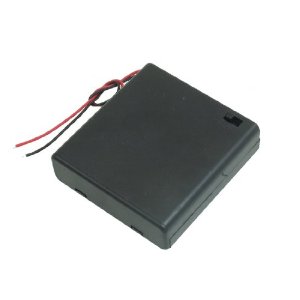
-3 x 6V battery packs (to hold 4 AA’s each) These are for the pump motors.
-3 x 3.7 V 6600 mAh Li-Ion Batteries for the foggers. (each powers 3 foggers)
Note: The foggers draw a lot of power fast, so Li-Ions really are the best choice, but they need to be used properly and safely. Definitely recommend reading this Adafruit overview of safe handling of Li-Ions!!
–Li-Ion Chargers. If you read the tutorial, you know that you have to use an appropriate charger for your batteries. I stuck with Adafruit, since that’s where I got the batteries. I bought a couple of these so I can charge many at once, they charge very slowly.
–JST connectors. These will receive the rechargeable batteries on your PCB.
-9V battery + connector for your Microcontroller
-Optional: Since I was going fully-rechargeable on this one, I also got a small Li-Po (3.7 V, 1200 mAh), to power my Arduino, but since these batteries output 3.7 V, you also need a powerboost to get it up to 5V. Again, this was worth it to me because I can reuse in other projects, if the project is a one-off for you, you can just power your Arduino with a 9V battery.
Dress Supplies:
–Lots of stiff fabric of your choice for exterior garment.
-Wire, range of gauges, you may have to experiment.
-Zippers
-A cheaper fabric that can be used as a slip underneath dress to hold electronics
-Velcro
-Elastic
The way I was able to get a large cloud of fog, as shown in above images, was by using 9 mini-foggers, installed around the body. Before you make multiples of anything, you need to get one version working well.
I followed this tutorial to get my first mini fogger going. Basically, what we are doing is just using the container from the vaporizer, without the intended battery for it. In order to hook up a different battery supply, we need to use the “mod” part linked to in the supplies. We are going to connect our power and ground to the part directly, and that will cause this whole piece to heat up. But we need to be really careful here not to cause a short! (don’t let positive and negative wires touch!) So following the Instructable I linked to, you’ll want to remove the middle part and solder your power wire to that, and then try to pop it back into the middle of the piece, with the insulator, which is kind of tricky.


The middle piece there is what needs to come out. Solder the wire to it and then pop it back in.

Photo Credits: Chimpusmaximus from Instructables
Solder your Ground wire to the outer piece. I wrapped my wire around and through the hole first for some mechanical strength.

The wire is going through and around the hole there, and then I soldered it
Once you have wires soldered to the Mod piece, you can slip the middle, power wire, through the aquarium pump tubing. The tubing needs to go right into the middle like that to pump air through, since no one is sucking on the vape to draw air out. But you will need to access that wire so somewhere further down the tubing make a small incision and pull it out with a pair of tweezers, and then seal the hole with hot glue or tape.

See my wire exiting the tubing
Fill your vaporizer with fog juice. I used roughly 1:1 glycerine (first-aid agent, can be found in drug stores) and water. And then you’ll want to wrap it with electrical tape, though maybe not too tight before you test it, because you may have to take it off and adjust you inner tubing.

The one on the left is taped up and ready to go.
So we now have a vaporizer filled with fog juice, and 2 wires exiting the vaporizer, power and ground, (power is coming out through the tubing). These will get connected to a power supply when you’re ready to test, that’s separate from the motor power. For testing, I suggest connecting your power supply to a breadboard, and plugging your fogger wires into the board also, so it’s easy to connect and disconnect.
Connect the free end of the plastic tubing to the aquarium pump motor. Then connect the motor to a power supply that’s separate from the fogger. For motors, I usually use a 6V battery pack with an on/off switch, so for testing you can twist the wires directly.

(There’s some liquid in my tubing I need to empty there, I left this whole thing sitting for about a year and condensation built up. But it still works!)
Turn on both power supplies, (motor and vaporizer) to test the fogger. The motor is really clear when it’s on because it’s noisy. If it doesn’t turn on check your connection. The vaporizer is harder to troubleshoot, you should hear it sizzling a little and you may be able to feel it getting warm, (though it shouldn’t get too warm.) If it doesn’t seem to be turning “on” and you’ve checked power supply, try taking the tape off and jiggling things around, that middle grommet may have slipped out.


I just used double A’s when I was testing, though eventually moved to rechargeable batteries for the foggers. Image on right shows breadboard once I had them working through relays, controlled by Arduino, more on that later.
Making Many
Once you have one working, you can make multiples! Before you start making multiples you want to think about where the fogger is going, how far it will be from the pump and power supply, and based on that decide how long your wires need to be. I recommend drawing it out.


I had originally thought about pointing the foggers outward, and I did try that, but I’m really trying to achieve a kind of cloud, and realized I got maximum effect if I could gather the fog together, so decided to have them all point up toward collar area.
Pic below shows how I ended up laying out my foggers, foggers near chest and motors near lower hips, (was trying to avoid anything too bulky near waist / middle, because hard to hide).

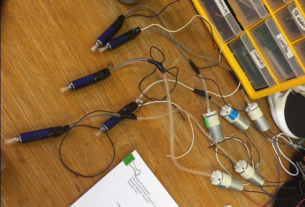
So, knowing how I wanted to lay the foggers out gave me an idea of how long I needed my wires and tubing to be. Here’s an example of five foggers all queued up and ready to go.
Next step is to be able to control your foggers through a microcontroller, so you can turn them on and off based on a sensor, a button, a timer, or whatever you’d like your trigger to be.
I did this by using relays to switch the power supplies on and off. The circuit consists of a relay, a transistor, a diode, and a resistor. You need 1 of these circuits to turn on the motor, and 1 to turn on the fogger, because remember, we have 2 separate power supplies. (This is annoying if you’re only making one, but will be helpful when making multiples).
My rule is always try it on a breadboard first. Here’s how the circuit looks on the breadboard:

The relay I used, which is an SPDT 5-12V has 5 legs. The side with the writing (facing away in above picture) has 2 legs. The blank side showing in this picture has 3 legs, but we will only use 2. The legs that are close to each other are N/O, N/C, normally open or normally closed. I’ll choose N/C, because I want the circuit to be normally closed, or off, unless activated. Check the datasheet on your relay if you aren’t sure which pins are which.
Here are two longer/better explanations of using a relay with an Arduino:
https://www.youtube.com/watch?v=AK-u71Lk5VI
http://www.instructables.com/id/Connecting-a-12V-Relay-to-Arduino/
Other important things to note are: we now have 3 power supplies: 1 Arduino, and 2 battery packs. The grounds between all of these are connected, but the positive terminals must not make contact!

The transistors are connected to the Arduinos, and these are what will flip on the relays. The relays allow our motor and fogger, respectively, to access the battery packs. (Make sure the packs are “on” if they have a switch).
So the code for testing this out is very simple. You just want to send a high to the digital pins connected to the transistors. Something like:
const int relay1 = 5;
const int relay2 = 9;
void setup() {
pinMode(relay1, OUTPUT);
pinMode(relay2, OUTPUT);
Serial.begin(9600);
}
void loop() {
digitalWrite(relay1, HIGH);
digitalWrite(relay2, HIGH); // turn both relays on
Serial.println(“relays on!”);
delay(5000); // wait for 5 seconds
digitalWrite(relay1, LOW); //
digitalWrite(relay2, LOW); // turn the relays off
Serial.println(“relays off!”);
delay(5000); // wait for 5 seconds
}
Note: I always send information to the serial, for debugging. This is simple code, but as things get more complicated, and something is supposed to turn on based on say, an “if statement,” I can check the serial and see if the program thinks it’s turning something on. If the Serial says “on!” and the thing is not on, I know the problem is with the circuit. If I check Serial and see that the fogger is never being activated, then I know there’s a problem with either the code or the sensor that is supposed to activate it.
Once you have a working version of the circuit above on your breadboard you can A). Celebrate and say you’re done! or B). Keep moving through this page to figure out how to add more foggers, a sensor, and lay the whole thing out for soldering.
Based on the batteries I outlined in the supplies section (switch to Li-Ion batteries for the foggers!), I found you can you load 3 fog machines and 3 motors per relay circuit, looking something like this:

The good news is, you can add in these extra foggers with no change to the code, we are still just communicating with 2 transistors.
To achieve my goal of having 9 of these, I had to have 3 versions of the above, so that’s 6 relays circuits total.
Regardless of whether you are doing multiple circuits, it’s a good idea to solder your circuit if it’s going into anything mobile.

The circuit on the left drives 3 foggers, the circuit on the right powers 3 motors.
So the above shows 2 circuits, they are both the same except that one will be connected to the 6V AA pack, and one will be connected to the Li-ion battery. They share a common ground, and they share 5V from the Arduino. I used those handy quick release screw terminals to plug in the wires from the motors and the foggers, because I wanted it to be feasible to replace them if needed.


These photos are harder to see, but the above circuit has a little white JST female connector soldered to the board, which allows me to plug in the lithium battery to that board, as you see in the picture on the right. (That battery is only 4400 mAh, so that circuit is actually only powered 2 foggers)

This board is just getting the 4 AA’s because it will power motors, and I connected it via screw terminals, so I could disconnect it easily. Batteries are heavy and you definitely want them to be removable, so avoid soldering battery cables to a board directly.
If you want 9 fog machines, as I did, you’re going you’ll need 6 little pcbs (each set of 3 machines takes 2 pcbs, 1 for motors 1 for foggers, it’s a confusing numbers game) and if you’re counting in my pictures, I had 7, that’s because I couldn’t get enough big batteries so had to separate the foggers further, just ignore that.
To solder all of the circuits across and to be sure they reach the Arduino and can sit comfortably, you definitely need to know where they are sitting in the garment or whatever you’re making. Here’s how mine ended up looking:

I’ll go into more detail on these decisions in the garment section, but the reason why I made a separate pcb for each little relay circuit was so that I could spread them out around the model. They are hard and bulky, so I felt like it was best to break them up. Also, that way I could keep the circuits near their respective fog machines. The most annoying/perilous part is connecting the ground and 5V power lines across them.

I soldered a double row of header pins to a pcb so that I could make my nano a plug and play the way Arduino Uno is. The solid core wire I used has done surprisingly well with not slipping out. The pins with headers are for the sensor, which is in the next part.
After you have everything soldered, check that the foggers are working still! If you added more circuits, remember to add more relay pins into the code too.
My fog machine is triggered by a galvanized skin response, which can be used as a measure of stress. These aren’t perfect systems, mind you, but they can detect a sudden change in the conductivity of the skin, which may mean the person is stressed or excited. This is the one I used:

From Seeed Studio who I love. I miss living in HK and getting free shipping from them. Only thing I don’t love is the big curly wire going down to her fingers, and I kind of wish I had taken it off in some of the photos…
This one is cheap and worked for me! I’m sure there’s more robust ones out there. They designed it to work with their I2C shield but it’s not required, I don’t use one, too bulky. We just need to connect the power to 3.3 V on Arduino (5V is occupied), Ground to GND (luckily we have an extra GND pin on Arduino), and SIG to an Analog pin (I used A0). There is a fourth pin that will not be used, as you can see from the grove wiki page:

As I said earlier, I soldered a double row of female header pins onto a PCB and connected them underneath. This allows me to take my Arduino Nano off the board if needed. It also allows me to plug things in without soldering. Luckily we can just plug this sensor right into pins mentioned above, 3V, GND and A0.

In an ideal world, I would have really planned this whole thing out and gotten circuit boards fabricated, or etched my own. But I didn’t do that, partially because I always think things are tests and then they get more involved… but so when using standard PCB I bridge gaps in the back by bending pins or using bits of extra wire, and occasionally using jumpers across the front. Looks messy but gets the job done.
The code linked below is what I used to trigger my fog machines by the sensor. You’ll notice it spends a lot of time in the set-up section reading initial values. This is kind of establishing a baseline and we will look for a sudden departure from this baseline as a sign of stress. Also in this code there is space for a button, I added one in so I could turn it on when needed for demos, and a “readLast” value that helps make sure it doesn’t stay constantly on. It needs to be off before it can turn back on again. Feel free to improve and please let me know if you do!
Also, my button is on when it’s value is “low” because I used a pull-up resistor. Here’s a good explanation of a push button. So the relays are getting written HIGH when button is LOW which may seem counter-intuitive…
Make a garment to hold electronics:
If you’ve made it this far, I commend you! I did this project over a year ago and am just now getting to the tutorial, and realizing how involved it was. Definitely not something to do in one sitting. Anyway, I imagine if you’re someone who reads tutorials it’s because you have your own cool project you want to do, and aren’t following this exactly, but just in case, I’ll cover this part: fitting everything into a dress!
My goals were to make sure A). We could get it on and off, so it had to be able to open in the back, B). It wasn’t terribly uncomfortable to wear C). The electronics were concealed as much as possible. D). The electronics were still somewhat easily accessible
So I figured the best thing to do was to load all of the electronics into an under-garment, or slip, and then have another garment go on top of that. It would have been cool to sew it all into one piece, and possibly more durable, but I wanted to be able to access everything for troubleshooting.
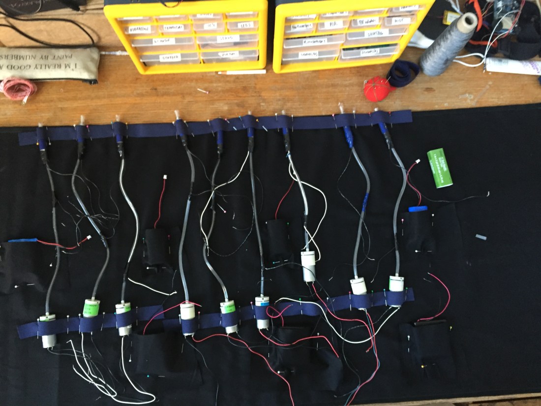
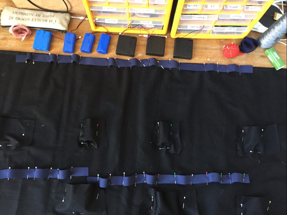
The undergarment is kind of like a smock with lots of pockets. The pockets are for the batteries, and then I used elastic to keep the foggers and motors in place.


I took one long strip of elastic and sewed it onto the garment, leaving little open loops along the way to slip the foggers and motors into. Before I got to the state you see in image above, I spread the garment out flat and pinned everything in place, so I could make sure it was all distributed well:
Then I took all the electronics out, and sewed the whole thing, mostly on a machine, but some by hand.
I have some batteries low and some high, but I wish I had just put them all down low. I think I did it like that to make sure they could reach the PCBs.

Then I added straps to the garment, used a cooler material for that since it will be visible, and I simply used velcro for the enclosure at the back.

I still needed to add my PCBs which was a challenge to do in a tidy way. I ended up sewing them to a piece of fabric that kind of acted like a belt, and then sewed this to the garment in only a few places, so I can remove if needed. Not as tidy as I’d like but very accessible and easy to switch out parts if needed.

There you can see the belt thing going across, and everything plugged in.
Note: Although we know this whole thing is a wearable fog machine, it definitely looks unfriendly to people who aren’t in the know, because it’s so bulky and there are so many wires, and the vaporizers look somewhat threatening. So take care with how you use it. I always cover it with an exterior garment when I bring it out in public. I also always have a camera crew and a smile, and am prepared to answer questions. It’s a wild world out there, I’m happy to make it weirder, but also want to be sensitive to the feelings of others, who might be frightened by this contraption. So please make fog responsibly, and check out the next section for ideas on how to cover it up.
Make an exterior garment to cover everything.
My whole design was based on the fact that the foggers were pointing up. I really wanted the fog to look like it was emerging out of the mouth of this thing. First we considered making it out of one piece of fabric, and that was going ok, but then I found the fabric pictured on the right and I really liked how space-agey it looked.


It was much stiffer and harder to work with though, so we ended up cutting it into two pieces and making a skirt and top.

Here it is all sewn up on my awesome model, Trona. There is wire in the top and bottom rim of the “shirt” to help it hold its shape. The skirt zips up the back and comes up quite hight. We put that piece on first, followed by the top.


One thing to note is that documenting fog is a challenge! I hate how the fog looks grey in the left picture and more like smoke. (Smoke vs. fog is an important distinction for me. Fog is ethereal, mystical, strange… Smoke has a much different reading) So I ended up sewing blue lights into the rim of the dress which helped give the fog a brighter, more billowy look. Natural light is also much bluer than most indoor lights, which lean toward yellow or green, and I did key it a little bluer in Photoshop. But no fog was added digitally! That’s all our little fog machine, plugging away.
That’s it for now. Please do let me know if you use a portion of this tutorial, would love to see how you implement it! Drop me a line at info@urbanarmor.org
